Check breadboard and prototype assembly here
Subparts
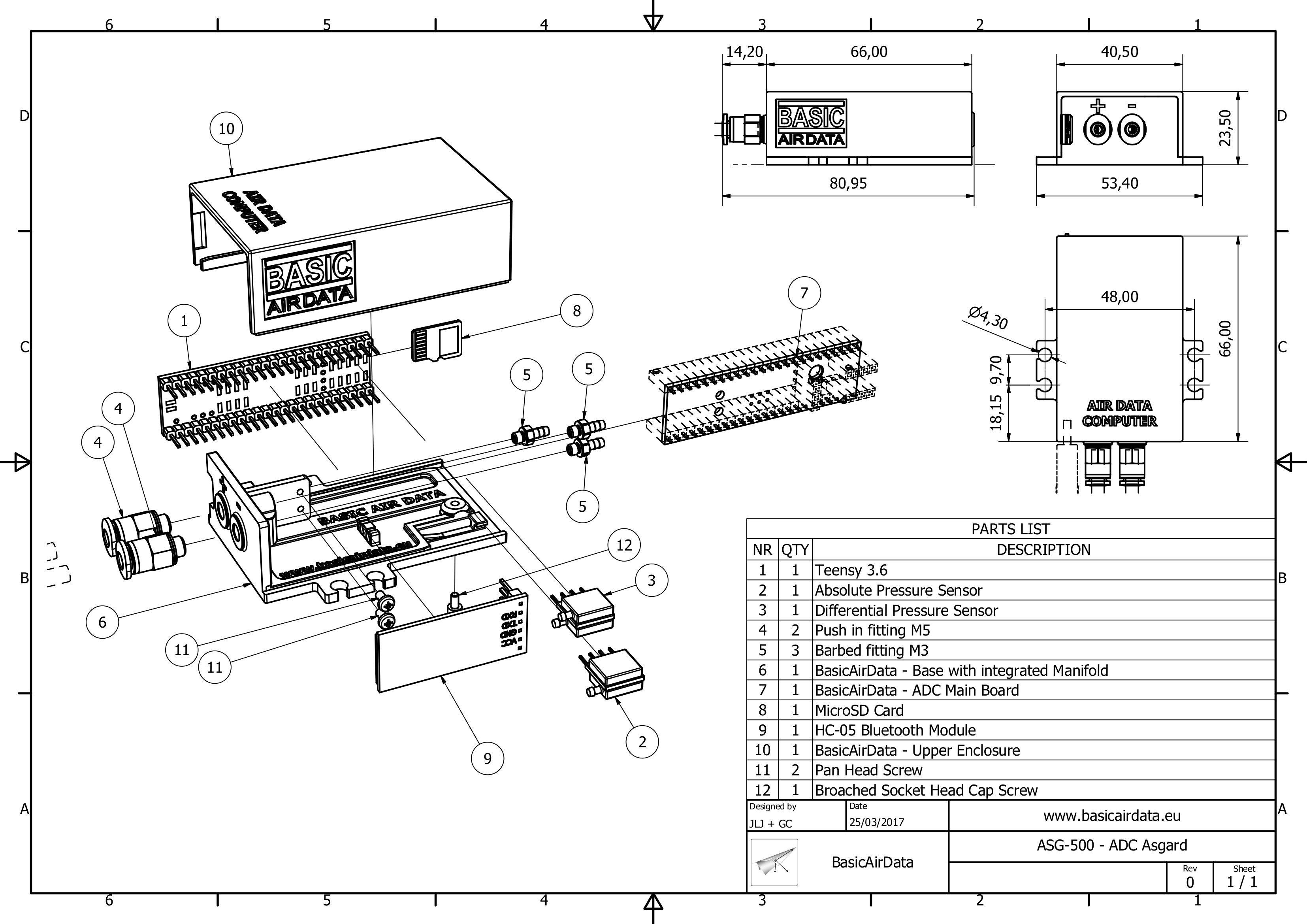
There are three main parts in an ADC. We have the enclosure, the electronic board, and the firmware. The ADC will perform lovely without the enclosure. Nevertheless, the suggested enclosure will help to attain an excellent mechanical and pneumatic performance. It’s comfortable to prepare before the construction all the materials and tools listed here below.
Required Materials
Electronic board; 3D Printed enclosure; Firmware
Tools required
Assembly of Electronic Board
Pictures from different builds
- Place the components on the side of the PCB with the text “Bluetooth over there”
- Weld the four resistors in a vertical position. You can put R1 and R4 on the socket side of the board and the remaining resistors on the other side. It’s okay also weld all the resistors on the connectors side of the board.
- Weld ABS sensor and DELTAP SIL female socket (you can also use female socket but electrical contact can be bad, you can even weld the sensors directly to the board for enhanced resilience)
- Weld BLUETOOTH female socket
- Cut the servo extension cable in two parts, leave at last 10 cm to the wire part with the female receptacle.
- Weld the wire to the board to OAT pads. Red to +3.3V, black to GND, white to A0
- Place the components on the side of the PCB with the text “Teensy side”
- Weld 2x female socket strip, 24 contacts, for the Teensy
- Besides the main printed board, you need to weld the temperature sensor to a wire to be able to measure outside temperature. +Vs –> +3.3V;Vout->A0;GND->GND.
Assembly of Enclosure
Holes on the 3D printed parts can be directly threaded, no drill is necessary.
ASG-001 – Asgard – Base with Manifold (download here the STL file and the Drawing):
- Remove eventual residuals of 3D print from all the cavities; a paper clip will help
- Make an M2 thread in the two holes that will hold the PCB fixing screws
- Make an M3 thread in the three internal holes on the manifold body
- Tighten the three barbed internal connectors
- Make an M5 thread in the two external holes
- Tighten the two push in pneumatic fittings
- With the Xacto like knife dent the enclosure in correspondence of the wire exit point.
ASG-002 – Asgard – Upper enclosure (download here the STL file and the Drawing):
- Remove eventual residuals of 3D print from all the cavities; a paper clip will help
- Make an M2 thread in the hole for the enclosure locking screw
Final Assembly
During the final assembly, you need to put the silicone tubing in place and close the electronics within the enclosure.
- Trim one silicone tube to 50 mm. Static port (-), absolute pressure sensor
- Trim two silicone tubes to 65 mm. Total pressure port (+) and Static port (-), differential pressure sensor
- Connect all the three silicone tubes to the barbed internal connectors of the enclosure base
- Route the silicone tubing through the plastic guides on the enclosure bottom internal part
- Push the absolute pressure sensor into its socket, be sure that sensor nipple is orientated toward the PCB center
- Push the differential pressure sensor into its socket, be sure that sensor nipples are orientated toward the PCB center
- Slide the board until the two small PCB holes are aligned with the enclosure base holes. Tighten down the PCB with two M2x6 mm screws.
- Mount the Teensy board on the PCB. In the correct position, the USB port should be on the opposite side of sensors sockets. During this operation be sure that the silicone tube from the manifold (+) is routed through the big hole on the PCB to the other side of the PCB
- Connect the 50 mm silicone tube from the lower Static port (-) to the absolute pressure sensor. Connect the 65 mm silicone tube from the upper Static port (-) to the differential pressure sensor higher port (PORT 1, far from the PCB). Connect the 65 mm silicone tube from the Total pressure port (+) to the differential pressure sensor lower port (PORT 2, near the PCB), passing through the PCB hole. Here you can find an image of silicone tubes routing
- Plug the Bluetooth module into the socket. Attention only the 4 central pins are used, 1 and 6 pins are unconnected
- Slide the upper enclosure part on the enclosure base, before closure verify that the temperature sensor cable is not mashed
- Screw down the case screw
- Insert the micro SD card
- Upload the firmware
- All done!
