In-flight measurement of the angle of attack is not yet a common application on small flying platforms. Despite that this information is useful for manned and autonomous and flight platforms, augmented stability, control flight systems and failure detection systems. A part post flight telemetry, angle of attack measurement can be correlated with real time flight performance indications. We will investigate here some basic aspects of angle of attack use.
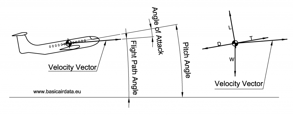
Angle of attack, AOA or ![]() , is the angle between the relative wind, oncoming air, and a fuselage fixed reference line. Sometimes the reference line is the fuselage center line [1]. Refer to Figure 1, here is show a planar trajectory of a generic aircraft in a generic flight condition.
, is the angle between the relative wind, oncoming air, and a fuselage fixed reference line. Sometimes the reference line is the fuselage center line [1]. Refer to Figure 1, here is show a planar trajectory of a generic aircraft in a generic flight condition.
You can see that the aircraft is flying with an attitude characterized by the pitch angle, ![]() . The pitch angle is measured with respect to the local horizon. Pitch can be effectively be measured with an Inertial Measurement Unit. Another angle of particular interest is the flight path angle
. The pitch angle is measured with respect to the local horizon. Pitch can be effectively be measured with an Inertial Measurement Unit. Another angle of particular interest is the flight path angle ![]() . This angle defines the angle between the current velocity vector and the local horizon. Pitch angle magnitude is equal to the sum of
. This angle defines the angle between the current velocity vector and the local horizon. Pitch angle magnitude is equal to the sum of ![]() and
and ![]() . Angle of attack is used to calculate the currently generated aerodynamic forces. Using a point mass representation for an aircraft in level flight, refer to the right of Figure 1, we can represent the aerodynamic forces acting on the plane as the
. Angle of attack is used to calculate the currently generated aerodynamic forces. Using a point mass representation for an aircraft in level flight, refer to the right of Figure 1, we can represent the aerodynamic forces acting on the plane as the ![]() lift vector and
lift vector and ![]() drag vector [2].
drag vector [2].
(1) ![]()
(2) ![]()
Where ![]() is the airspeed and
is the airspeed and ![]() is the wing area.
is the wing area.
Apart the aerodynamics forces, we have the thrust force from the engine and the weight force ![]() . In our example the thrust line is coincident with the fuselage axis and weight force is pointing downwards.
. In our example the thrust line is coincident with the fuselage axis and weight force is pointing downwards.
In Equation 1 and Equation 2 the relationship between ![]() , wing coefficient of Lift
, wing coefficient of Lift ![]() and wing coefficient of Drag
and wing coefficient of Drag ![]() is needed. It’s possible to correlate the aerodynamic performances of the wing to that of a wing section [3], we don’t treat any detail here.
is needed. It’s possible to correlate the aerodynamic performances of the wing to that of a wing section [3], we don’t treat any detail here.
Wing section coefficient of lift ![]() and drag coefficient
and drag coefficient ![]() values in function of Re,
values in function of Re, ![]() and
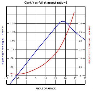
and ![]() can be found under the form of the lift and drag polar diagram Coefficient of lift of the wing section increases with
can be found under the form of the lift and drag polar diagram Coefficient of lift of the wing section increases with ![]() , when the angle of attack reach a determined value
, when the angle of attack reach a determined value ![]() the flow over the wing detaches then the lift sharply decreases; we say the wing section is stalled. To avoid the stall we shall fly under the stall angle.
the flow over the wing detaches then the lift sharply decreases; we say the wing section is stalled. To avoid the stall we shall fly under the stall angle.
In level flight and low angle of attack we have ![]() . The plane can follow it’s level flight as long as we have a valid
. The plane can follow it’s level flight as long as we have a valid ![]() tuple. If we increase the angle of attack the lift magnitude will increase and the airspeed can be decreased too. If we increase the angle of attack further, the lift vector is pointing not anymore straight upward but deviated of
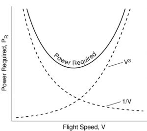
tuple. If we increase the angle of attack the lift magnitude will increase and the airspeed can be decreased too. If we increase the angle of attack further, the lift vector is pointing not anymore straight upward but deviated of ![]() from the vertical, then the engine thrust will help us to maintain our attitude and we can eventually reduce further our airspeed. We can reduce the airspeed further increasing the angle of attack and thrust stall, eventually we will reach a point when the wing will stall. During a stall, we will loose control authority and no engine thrust can help us to recover our attitude. If we collect all this data, and more, in a graphical form we obtain the power curve for that plane, a typical power curve in Figure 3 for MIT.
from the vertical, then the engine thrust will help us to maintain our attitude and we can eventually reduce further our airspeed. We can reduce the airspeed further increasing the angle of attack and thrust stall, eventually we will reach a point when the wing will stall. During a stall, we will loose control authority and no engine thrust can help us to recover our attitude. If we collect all this data, and more, in a graphical form we obtain the power curve for that plane, a typical power curve in Figure 3 for MIT.
A likely scenario where the pilot or the autopilot try to minimize airspeed is the landing, a correct use of angle of attack can help to achieve a comfortable landing on spot.
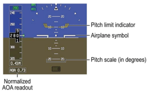
With airplane aerodynamic specific data and the angle of attack measurement, we can have an effective pitch limit indicator PLI. A pitch limit indicator informs the user about the current difference between ![]() ) and the current
) and the current ![]() . In many commercial airplane the pitch limit indicator is integrated within the glass cockpit, as shown in Figure 3; with this setup the pilot have a real-time indication of how much can pull on the column.
. In many commercial airplane the pitch limit indicator is integrated within the glass cockpit, as shown in Figure 3; with this setup the pilot have a real-time indication of how much can pull on the column.
The maximum pitch angle is correlated with the maximum climb rate achievable ![]() at a certain time
at a certain time ![]()
![]() . The knowledge of such an information is necessary and useful for trajectory planning [This ref Eq.3]. Planning is intended here offline or real-time.
. The knowledge of such an information is necessary and useful for trajectory planning [This ref Eq.3]. Planning is intended here offline or real-time.
Using both the angle of attack information and an accurate plane analytic model we can individuate pitot failures or a error in payload weight indications. Let’s consider a really simple example scenario. We know, from the plane math model and from the airspeed measurements, that the angle of attack during current maneuver should be equal to 2 deg. However, we measure 1 deg instead. From this information, we can say that probably we have a malfunctioning pitot leading to wrong airspeed measurements.
The angle of attack, PLI is used also to manage upset recovery, obstacle clearance and can be used to increase wind shear awareness [2] and management. It is to be noted that to be useful the angle of attack information should be accurate, one degree of uncertainty is not acceptable in many applications.
Think now about a far common situation, for example, when a landing on spot is desired. In steady air, if the plane is piloted following a constant ![]() descending path then it will flight along a constant pitch trajectory. With such a trajectory it will be possible to control both
descending path then it will flight along a constant pitch trajectory. With such a trajectory it will be possible to control both ![]() and landing point. Speaking of commercial planes the angle of attack information can be used to reduce the risk of tail strikes [3].
and landing point. Speaking of commercial planes the angle of attack information can be used to reduce the risk of tail strikes [3].
Another useful graph is the glide polar. That graph correlates the sink rate to the current airspeed. With such an aerodynamic information we can determine the best glide angle. Apart the advantages for the gliders, following the best glide angle can be really interesting for motor planes that are facing a non powered landing. If that information is available, in a standard cruise situation, the cruising angle of attack and the airspeed can be set to attain optimal fuel consumption.
Many different uses of angle of attack measurement have been exposed. One of the most common uses, neglected till now, is the aerodynamic parameters identification [3]. Aerodynamic parameters are needed for the use of advanced fly control, planning systems and failure detection and recovery. The topic has an explosive complexity and deserves dedicated articles.


