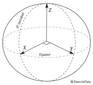
Figure 1 – ECEF Coordinates
When referring to aircraft position, velocity, acceleration, orientation and angular velocity, the coordinate system in which they are expressed should always be mentioned. While frames of reference are arbitrary and everyone can use a different one to get the same results, it is convenient to use a common one. This makes it easy to share calculation procedures and data and compare them directly. Also, let’s not neglect the fact that some coordinate systems are more intuitive to work with and are more suitable for specific work cases.
A few options are available, when it comes to choosing a coordinate system for aircraft or airborne systems in general. We will use the North-East-Down system (NED), due to its popularity and ease of use[1].
As the Earth is moving and rotating, we need a reference frame that is attached to the Earth itself. This is mostly imposed by the common characteristics of flight missions, which are expressed in terms of ground features (eg surface waypoints and landing sites). A common right-handed coordinate system is the Earth-Centered, Earth-Fixed frame (ECEF). Its origin is the center of the Earth. The X-axis points to the intersection between the Equator and the Prime meridian (latitude 0°, longitude 0°), the Y-axis points to 0° latitude and 90° longitude and the Z-axis points to the North Pole (latitude 90° along the axis of rotation of the Earth).
To use this coordinate system, the shape of the surface of the Earth should be analytically defined and a widespread definition is the WGS-84.
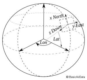
Figure 2 – NED frame
At this point, we will make two working hypotheses. First the curvature of the Earth will be neglected. This is a valid hypothesis when the airborne vehicle operates over a small area. The second notable assumption is that the atmosphere (the air mass over the Earth) is not moving in relation to the surface[2] (Par. 2.1).
Next, we need a local reference frame or a local geographic frame. That frame is necessary in order to describe local trajectories and altitude. We can use local coordinates because the proposed reference system is used under the flat Earth hypothesis. This assumption will not hold when the vehicle travels far away from its origin, in which case the system equations will not describe reality adequately.
To this goal, a plane tangent to the surface of the Earth is defined and is called Local Tangent Plane (LTP). To describe quantities in relation to the LTP, we will use the North-East-Down (NED) convention. In this convention, the “North” axis points North in the local meridian direction and the “East” axis points East in the local parallel direction.
These directions span a Cartesian plane on the LTP. The final, “Down” axis is perpendicular to the other two axes and points towards the Earth, to complete a right-handed coordinate system. Note that the “Down” axis doesn’t point to the center of the Earth, but is defined by the other two axes and its direction depends on the latitude and longitude of the origin of the NED frame. Refer to the Figure 2 for a graphical definition.
The origin of the NED frame is fixed in ECEF coordinates. It can be chosen arbitrarily at a point on the surface at the operational site of the aircraft.
Next, we introduce the “body” frame of reference that has its origin coincident with the center of gravity of the aircraft, thus it moves with the aircraft itself. Refer to the Figure 3. The X-axis of the body frame is pointed toward the aircraft nose, the Y-axis is along the right wing and Z-axis points down. In the case where the aircraft is not rotated, the body axes have the same orientation as NED axes.
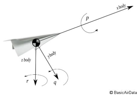
Figure 3 – Body frame
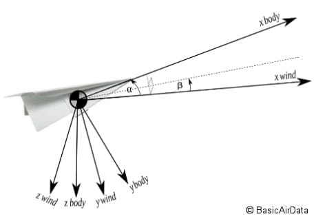
Figure 4 – Wind frame
Rotation along body X-axis is called  or roll, rotation along Y-axis is called
  or pitch and rotation along Z-axis is called
  or yaw. The set of those three rotations (roll, pitch, yaw) is called “Euler angles” and describes the orientation of the aircraft in relation to the NED frame.
The body frame can be aligned with the NED frame through the Euler angles in a specific sequence. Starting from the NED frame, we perform a rotation around NED Z-axis by the yaw angle. Next, we rotate this new frame by its Y-axis by the pitch angle. Finally, we rotate again by the new X-axis by the roll angle. The resulting frame is the body frame.
The body frame might be useful for a multitude of applications, but it is not convenient to work with when it comes to calculating aerodynamic forces and moments.
To handle aerodynamics we define a “wind” frame that is pointed directly into the relative wind direction, as depicted in the Figure 4. The origin of the wind frame is coincident with body frame origin and its orientation is defined by the angle of attack  and the angle of sideslip
  .
.
Starting from the body frame, a down-positive rotation about the body Y-axis by the angle aligns the body Z-axis with the wind Z-axis. Afterward, a right-positive rotation about the Z-axis of this new, intermediate frame by the angle aligns the axes with the wind frame.
0 Comments