Go to this page here for the latest Air Data Computer release
Please consider using the latest release of ADC. Amaranth is a closed project.
Here you find the link to the ADC Amaranth i2 pictures.

Hardware was tested. Basic test firmware was published. To build your own unit go to the download paragraph. Make at your own risk. Good idea is to check the GitHub repo for new releases.
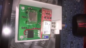
Good news is that the ADC prototype is working. Custom PCB and 3D printed case are completed. The unit is Bluetooth enabled and can be interfaced with an Android device with the provided library. This is not a commercial project, we will publish results when and if we have the necessary resources. We will be very glad if you share your built or your customization with us.
Our ADC is designed for DIY makers and experimenters, our primary goals were to provide a good performance, content costs and simplify every manufacturing operation; to assembly the unit you will need few hand tools and about three hours time. Selected components are available through the internet and we tried to use as much as COTS as we can. Proposed unit is intended for a bench top usage, the case is able to manage different configurations of sensors and to expose the microcontroller pins; the unit can be used for airborne applications on medium and big scale flying platforms. Power can be provided through the micro-USB connector, so it’s possible to use widely available cell phone power banks. To galvanically insulate the ADC you can use the Bluetooth module and power the unit with a battery pack.
We will refer here to the most typical application that is to use the unit to get the current airspeed. Other notable applications are the use as pitot-static calibrator and as flow computer. The files to print your case and PCB are provided, you can do it by yourself or use an online print service. To assemble the printed circuit board basic soldering skills are needed. In the following sections, we will introduce all the needed components and afterward we will provide assembly instructions. Prior to assembly is better to read through all the available information.
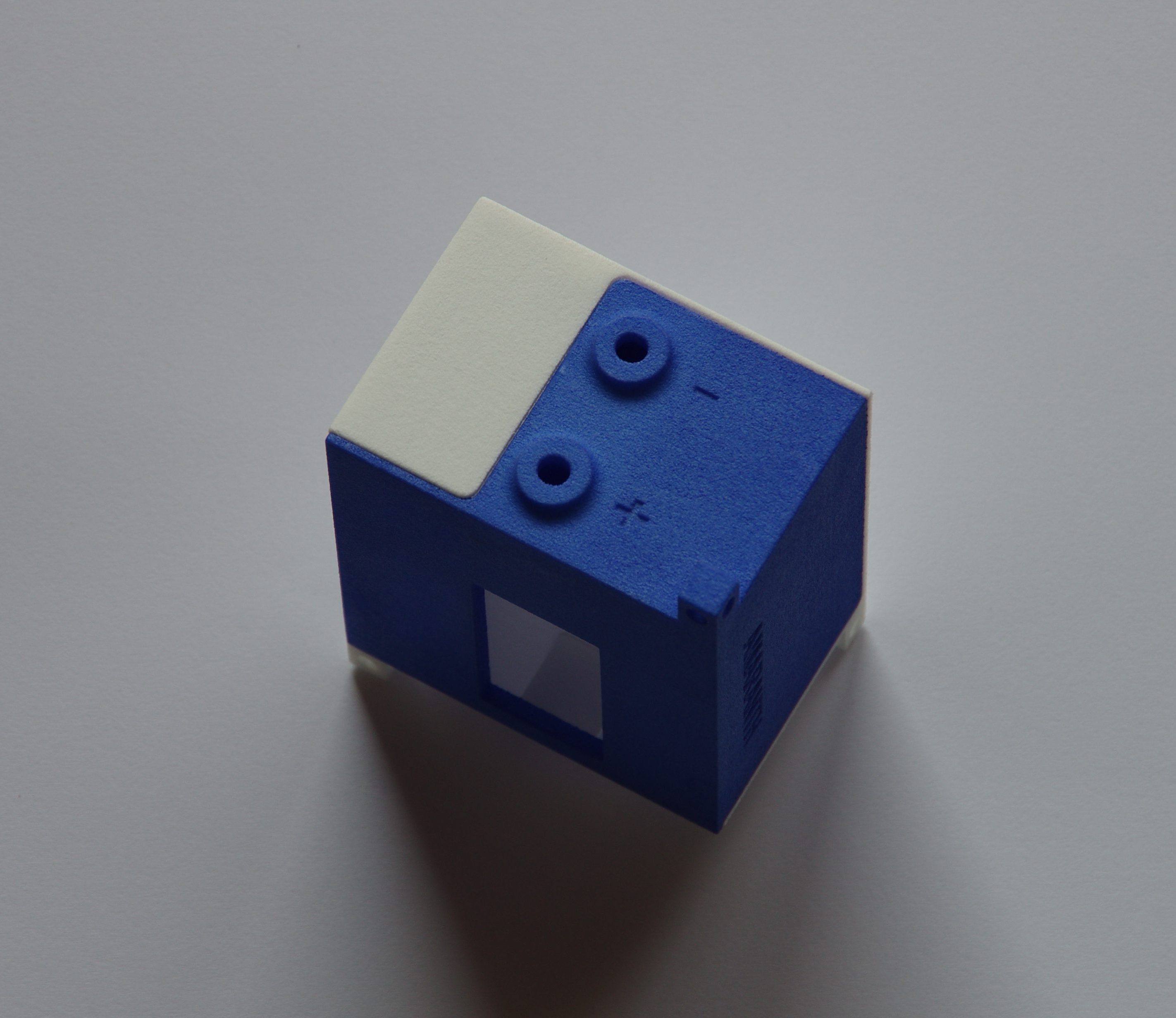
Amaranth i2 case
Reference Configuration
Since it is possible to change some characteristic of the unit selecting different hardware, we propose a reference configuration. The reference configuration will have the following characteristics.
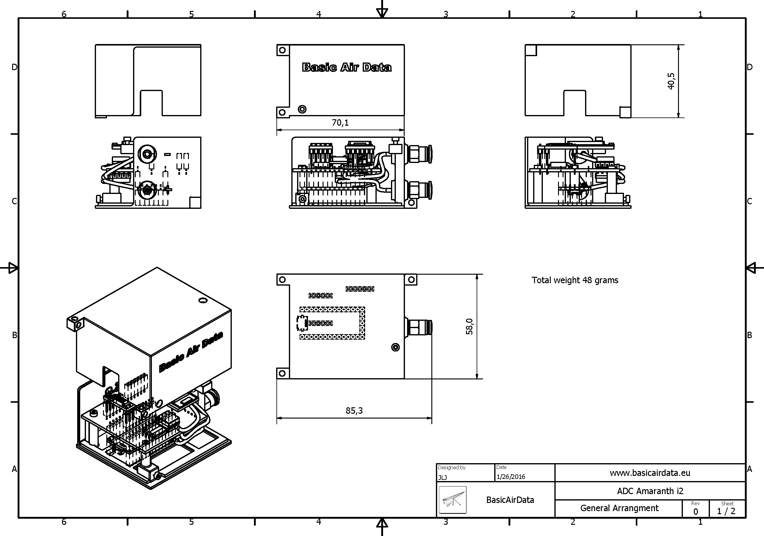
Overall weight : 48 grams
Overall dimensions : Without push in fittings, 58×40.5×70.1 mm. With push in fittings, 58×40.5×85.3 mm
Assembly time : About 3 hours
Overall cost : 170 Eur (February 2016)
Power and Supply Current : Power to the ADC is supplied through a standard micro USB port, the same port is used to transfer data. Without Bluetooth module 15 mA. With Bluetooth module in standby 40 mA. With Bluetooth module in RX mode, typical 50 mA and max 75 mA. With Bluetooth module in TX mode, max current case 115 mA and typical current case 80 mA. The maximum drain case is about 0.4 W, 1440 J in one hour. A medium/small power bank rated 2200 mAh should be able, at rough, to provide  . 39600/1440=27.5 hours of battery time in the worst, never likely to happen, case. Let’s pretend the TX is on all the time at 80 mA, with the same power bank our autonomy will be 41.6 hours. Let’s pretend now that our device is, most realistically but still severe use case, either in TX mode or in RX mode; the average current drain will be 65 mA. The estimated endurance will be now 51.3 hours. Without the Bluetooth module, our autonomy will be 222.2 hours.
Ratings: Maximum measurable IAS @ standard conditions and  .
. /382.06 km/h.
 /120.82 km/h. Raw sensor Range (-1,+1) Psi. Sample speed 50 Hz (user selectable).
Altitude, ISA (<4000,  ) MSL.Raw sensor Range (0, 160000)Pa. Sample speed 50 Hz (user selectable). Uncertainty , 0.056m @ 50 MSL and 0.064 m @ 1000 MSL.
Bluetooth : Present
Micro SD Card Reader : Present + SD Card 4GB
Temperature measurement : Not present but advisable in many applications. May require an OAT probe. Implementable with semiconductor based thermometers, that code and hardware work on the ADC, attention this is a low-frequency solution.
Pictures
Here you find the link to the ADC Amaranth i2 pictures.
General Arrangement Drawing
Basic Use
To provide airspeed information the unit needs to be used with a Pitot-Static tube or with a pitot tube and a static pressure port; no need to be custom made, third party units are fine too. The unit is fitted with two push-in pneumatic ports for 4 mm tubing. On the unit one pressure port is identified with “+” and one with “-“, corresponding to the total pressure port and the static pressure port. Those ports should be connected to the pitot-static tubing, plus port is to be connected to the line that arrives from the pitot tip and minus port from the line that arrives from static ports. You find the Basic Air Data 8mm Flanged pitot here or the removable pitot flange arrangement in this link. Once connect the ADC to a probe you can read your airspeed via a USB connection or via Bluetooth connection.
Electronic Schematic
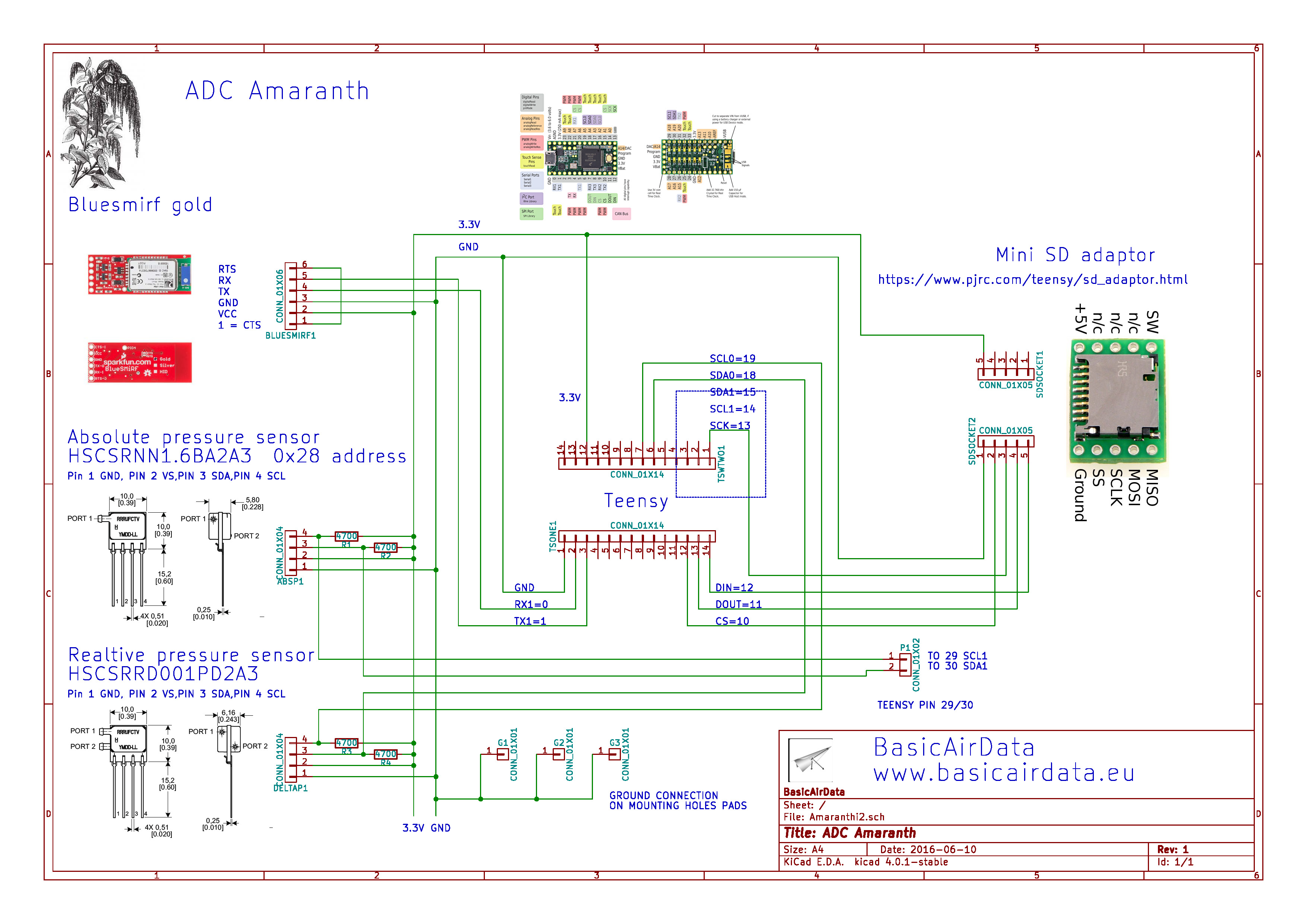
Amaranth i2 Schematic
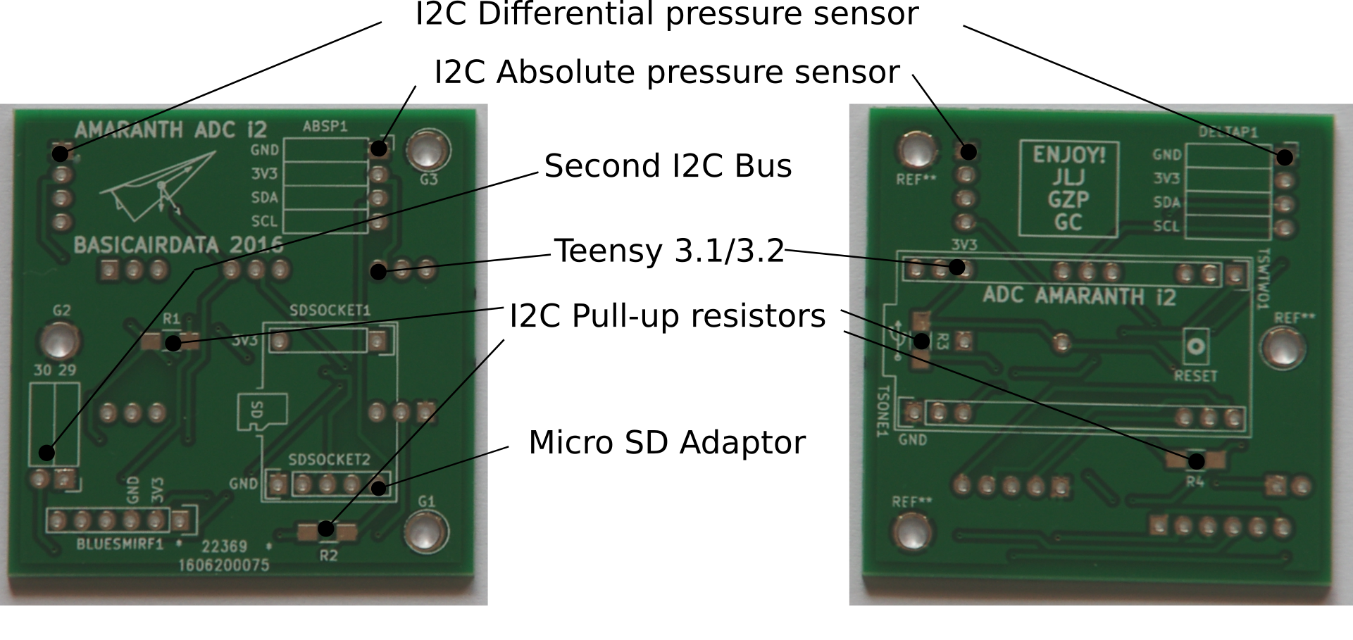
Pinout of the PCB
Download Necessary Set of Files
-
- STL files to To 3D print the CASE [download id=”1680″]
-
- EDA files to print the Printed PCB [download id=”1685″]
- Sockets and resistors needed to complete the PCB [download id=”1695″]
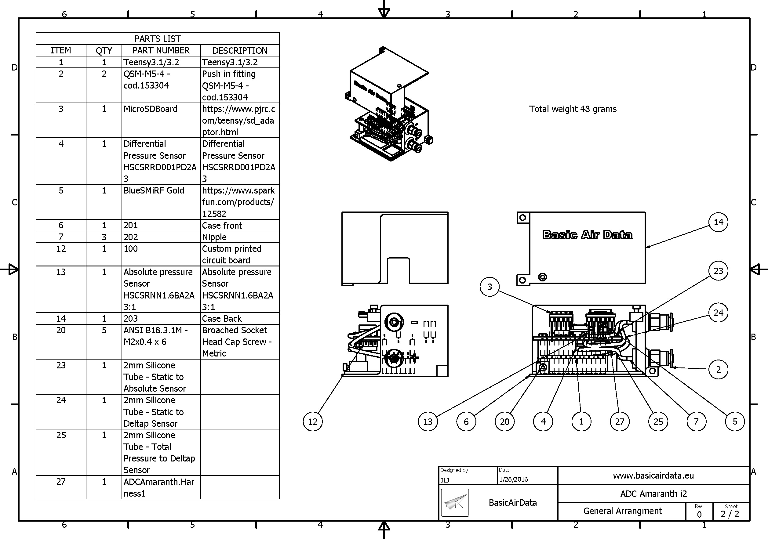
Bill of Materials
Based on your application you can decide to not to use some hardware, like a SD card reader or a Bluetooth interface. We show here our reference setup.
ADC is composed of three main subsystems PCB, CASE, and COTS.
CASE Related Material
You can print the 3D case with the files provided in the download paragraph. We’ve used Shapeways to print the parts.
-
- CASE Front – 201 – Item 6 – Prototype printed on Shapeways
-
- CASE Back – 203 – Item 14 – Prototype printed on Shapeways
-
- N.2 M2x6mm socket head cap screw (Phillips cross pattern)to close the case – Item 20 –
-
- N.3 M2X6 mm socket head cap screw (Phillips cross pattern) to fix the PCB on the support pillars / It is possible to use also self-tapping screws or screws with flanged head – Item 20 –
-
- N.2 Festo – Fitting QSM-M5-4 – cod.153304 or equivalent like those of Metalwork -Item 2 –
- N.1 50mm of stainless/bronze/aluminium pipe. Two millimeters of external diameter. You will need that pipe to build the pressure nipples – Item 7-. As an alternative, you can buy syringe needles Gauge 14/14.5(1.8 and 2 mm of outside diameter), a couple of them long 40mm will be sufficient.
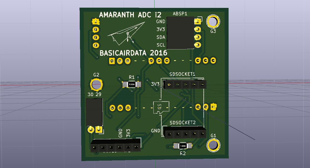
Amaranthi2 PCB Front, render by Kicad
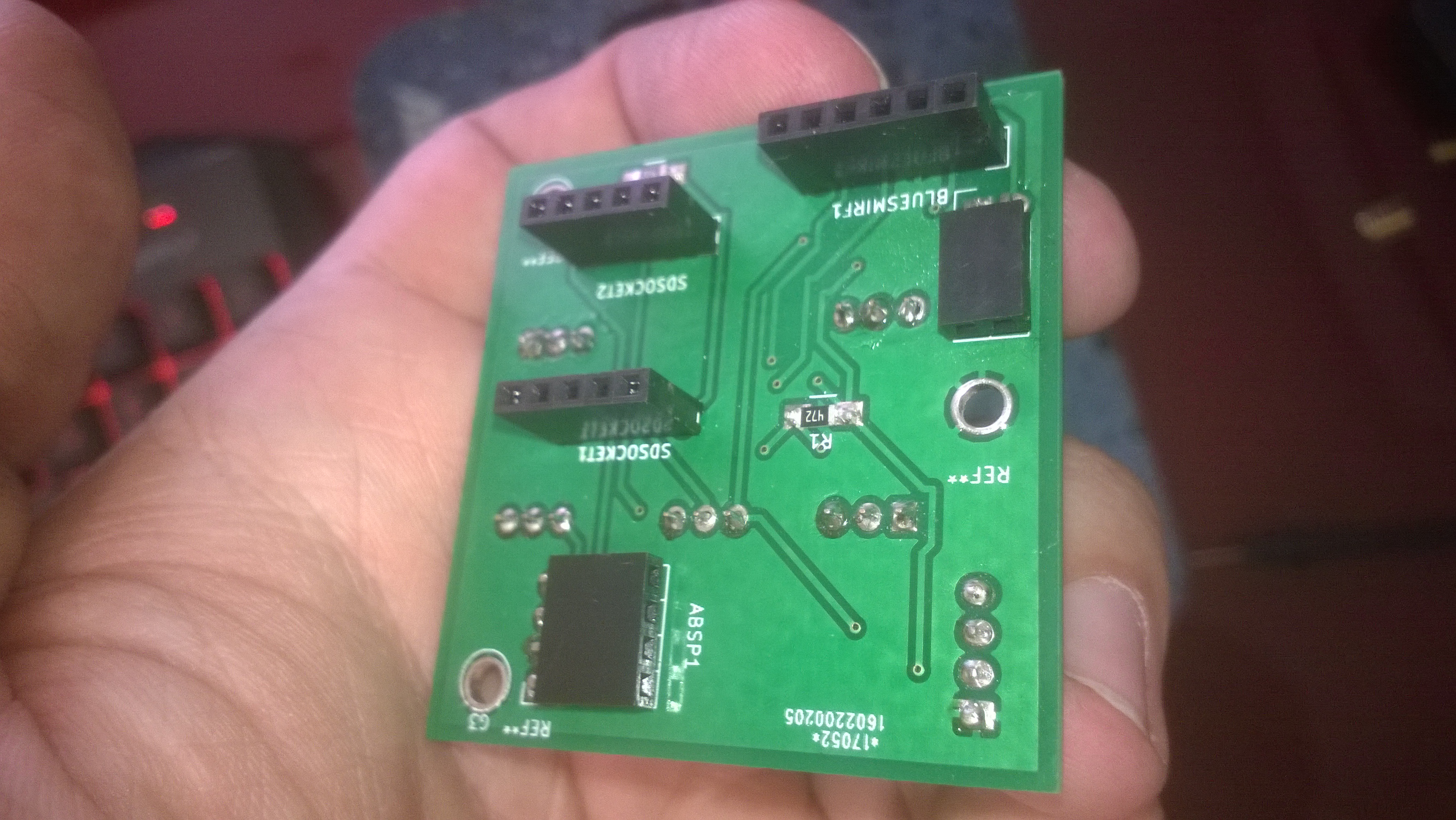
PCB Related Material
The PCB is a simple connection board. You can print it by your own using the source Kicad files [download id=”1685″]. The output from the software in shown in pictures.We’ve used the online print service by DirtyPCB, here is the link to the board.
To complete the board you need many sockets and four SMD resistors. Here you find the detailed list of materials [download id=”1695″]. The items in the list can be bought online, for example on Digikey. Alternatively, it is possible to buy general purpose longer sockets and trim they down, this solution is on the cheap side.
Commercial off the Shelf Components
The pressure sensors, the Micro SD adapter, the Bluetooth interface, and the Teensy Microcontroller should be bought online. Availability is worldwide good. Regarding pressure sensors, the user has the possibility to select the pressure scale to fit their need. That allow the unit to handle, for example, a very low airspeed.
-
 The differential pressure sensor is the Honeywell HSCSRRD001PD2A3 – Item 4-. See for example this online shop
- The absolute pressure sensor is the Honeywell HSCSRNN16BA2A3 – Item 13. See for example this online shop
-
- Micro SD adaptor is the one from PJRC, remember to buy also an SDCard (2/4GB are sufficient and manageable by the unit)
-
- Bluetooth interface board is the BlueSmirt Gold/Silver from Sparkfun
-
- Teensy microcontroller from PJRC or local dealer
-
- You will need at least two straight breakaway headers(40), pitch 2.54 mm, that will be soldered to the COTS components
- We advise using stackable headers for the Teensy board, it is of course possible to use straight breakaway headers. For the Teensy we need two 8 pin stackable socket, two 6 pin stackable socket and one 5 pin socket
Required Tools and Glue
-
- Tap tool with handle. M2x0.4 and M5x0.8 taps
-
- Screwdriver for you selected M2x6mm socket head cap screw. Usually, you need a Phillips type blade #0/1;small screwdriver with cross pattern blade
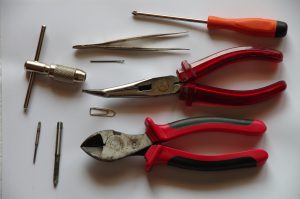 Cut off disc tool and rotary tool. Dremel like (Alternatively, you can use a miniature hand saw or a miniature table saw)
- Soldering iron with wire and soldering flussant
- Precision plier to hold down SDM resistors when soldering
- Plier
- Vice or clamp
- Adhesive tape
- Paper clip
- 2 mm drill bit. The necessity of this part is dependent on the fabbrication tolerances. Sometimes it will not be used
- Sandpaper, 200 grit
- Few centimeters of plastic 4 mm tube suitable for the push in fittings, we need that for preliminary testing
- 200 mm of silicone tube 2 mm of outside diameter , internal diameter should be suitable for a good coupling with the barbed ports of the sensors. About 0.9 mm are ok for selected sensors
- Two M/F or M/M jumper cables

- Bi-component epoxy glue, 10 grams (you will leave a couple of grams on the ADC). Thirty minutes cure time resin is comfortable to use during assembly operations. RC Hobby grade 1:1 mix ratio resin is good
 Subsystems Assembly

Follow the links and prepare each subsystem for the final assembly
PCB, CASE and COTS preparation
Final Assembly
Few operations are needed here. All the COTS components should be plugged into the proper socket. Pay attention to not invert the mounting direction of components. In particular for the Micro SD adaptor follow the drawing on the PCB, the SD card slot shall be placed facing the interior of the PCB.
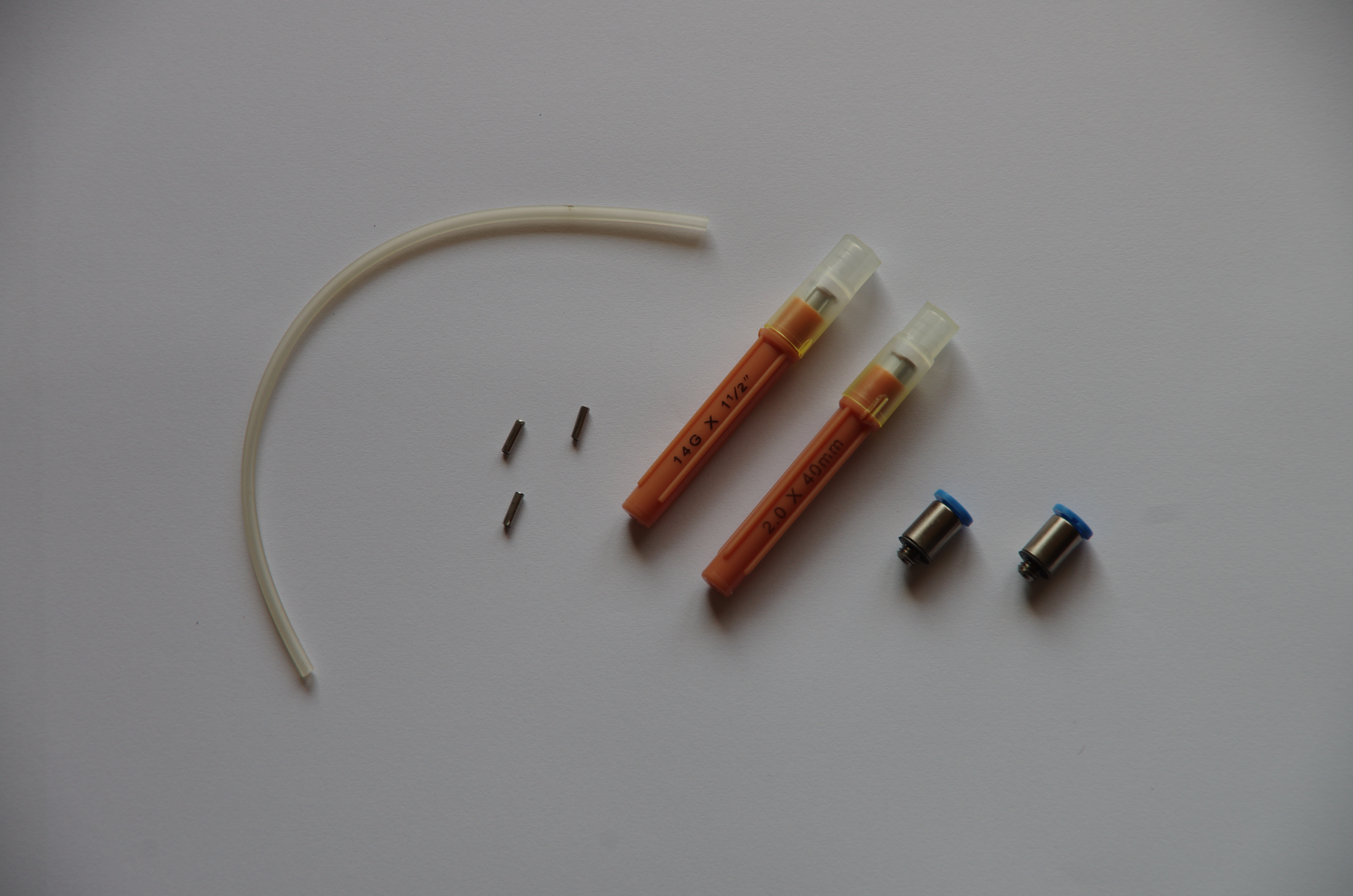
Pneumatic components for Amaranth i2
The Teensy board correct orientation is indicated on the board by the position of the Teensy USB port and the reset button, the USB port should be directed to the outside of the PCB. Pressure sensor has the pressure ports on the outside part of the board. Further, each pin 1 of a socket has a square pad on the PCB. Once all the components are placed you can fix the PCB to the case front tighten the three screw on the PCB support pillars. Cut three silicon tubes of 52 mm of length -Item 23, 24,25-. Connect the absolute pressure port to the upper left nipple on the case. Connect the upper port of the differential pressure sensor to the right upper nipple on the case. Connect the lower port of the differential pressure sensor to the lower nipple on the case. Close the case with the two remaining screws. Build complete.