In our continuing effort to enable the DIYer to build his own Air Data Computer, we’ve organized some code into a microcontroller-oriented standard library. The code is intended for the Teensy and Arduino boards. To let the user understand how the library can be used, we have prepared some fully working examples ([download id=”2584″] ).
This article presents the installation and operation of the library for a Teensy 3.1/3.2 board as a temperature logger.
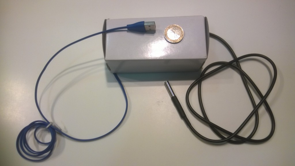
Figure 1 – Logger in a cardboard case. You can recognize the USB cable and the temperature probe
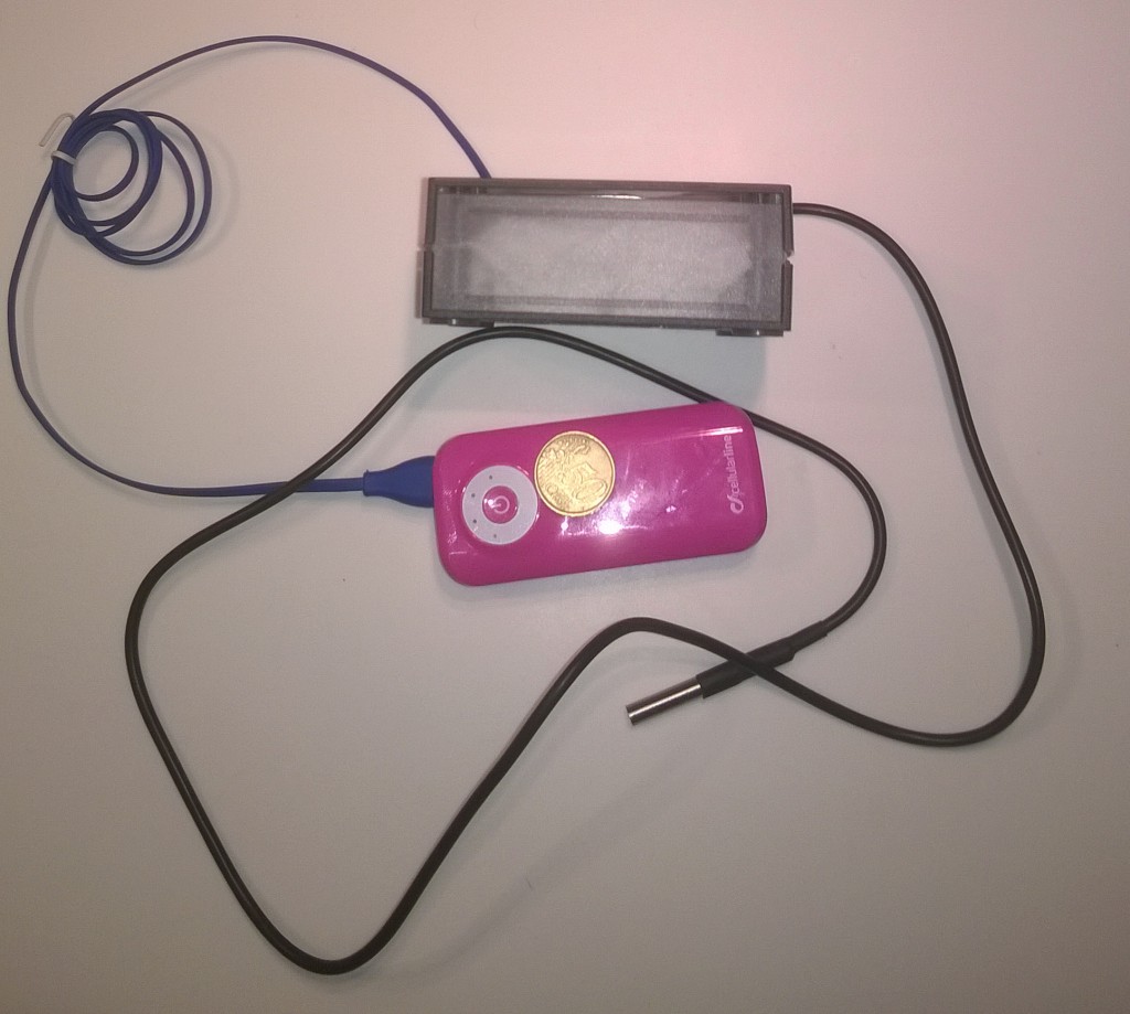
Figure 2 – Logger in a plastic case. The unit is powered by the pink USB charger
Main functions of the logger
This temperature logger is able to:
- Record temperature readings to a Secure Digital (SD) memory card, as well as forward the measurements via USB
- Accompany the recordings with a corresponding time stamp
- Calculate certain physical properties of dry air using the AirDC library
Each data packet contains the following information:
- Air density,

- Air temperature (
 )
) - Air temperature (
 )
) - Air temperature measurement uncertainty (
 )
) - Reference pressure (
 )
) - Viscosity (
 )
) - Timestamp (year, month, day, hour, minute, second)
- Program execution time (
 )
)
You can find two example SD log file attached with this article or in the following links (.csv, .ods)
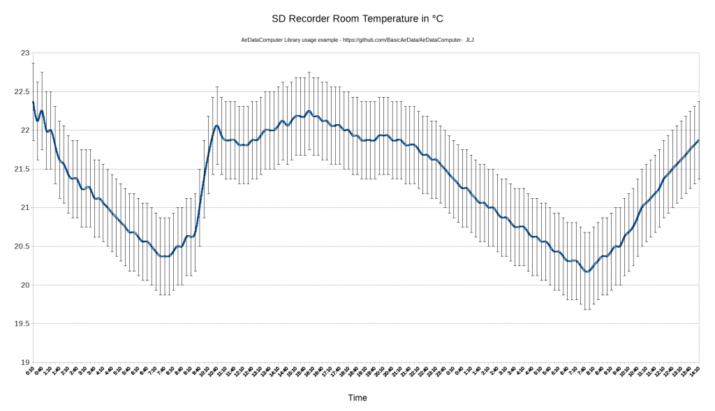
Figure 3 – Temperature graph from Logger data
Prerequisites and Components
To build a logger identical to the one presented, you will need the following hardware and software and basic soldering skills.
Hardware
- 1 x Teensy 3.1/3.2 microcontroller (Figure 4, pinout information)
- 1 x DS18B20 temperature sensor, a low sampling rate digital temperature sensor from Maxim with a nominal accuracy of 0.5 (Figure 5)
- 1 x Portable, battery powered USB charger with microUSB plug (Figure 6)
- Some thin, multi-strand wire
- 1 x 32.768Hz quartz crystal, to enable the real time clock operation of the Teensy (RTC) (Figure 7)
- 1 x SD Card Adaptor for Teensy and SD card (Figure 9)
- 1 x 4.7kΩ/0.25W resistor, regardless of accuracy
- 1 x 3V coin battery and battery holder, to maintain RTC in case the USB charger is disconnected (Figure 8)
Software
- The Arduino IDE
- A working installation of Teensyduino
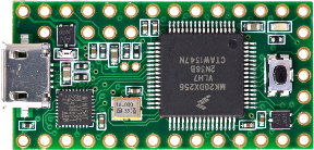
Figure 4 – The Teensy 3.1 board
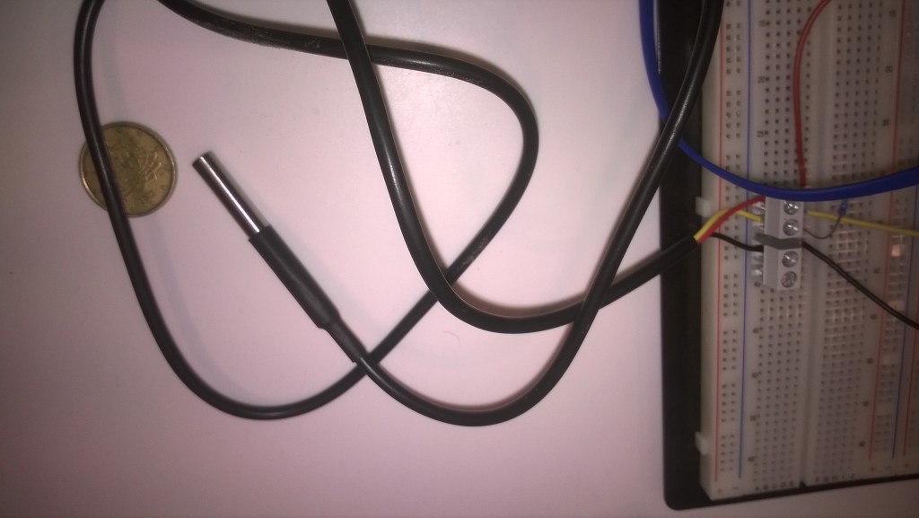
Figure 5 – DS18B20 sensor with stainless steel sheath and cable. It may also be used in its bare, standard package e.g. TO-92
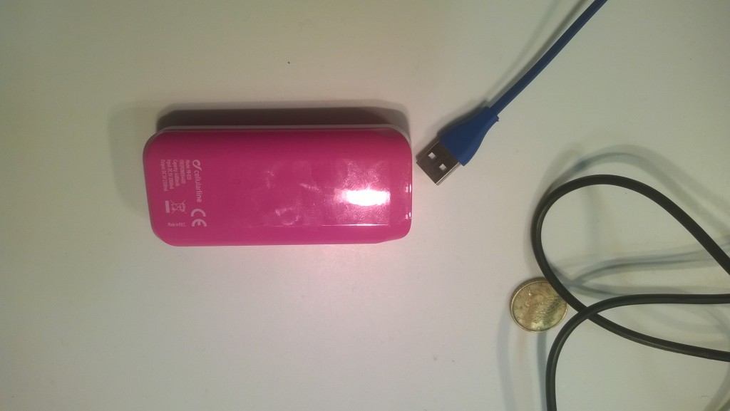
Figure 6 – Standard USB phone battery charger
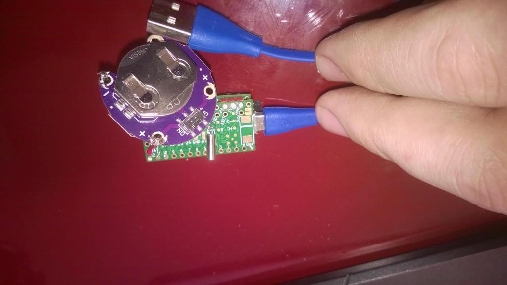
Figure 7 – A quartz crystal, soldered on Teensy 3.1, resembling as a small, shiny cylinder
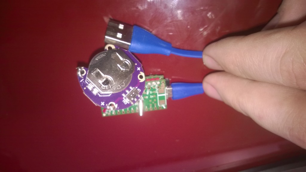
Figure 8 – Coin battery cell holder, soldered on Teensy 3.1
Figure 9 – Soldered SD card adaptor
Library Installation
Download and install the latest public release of the AirDC Teensy library from our Github repository or here [download id=”2584″]. Once downloaded, place the whole AirDC folder within your Teenyduino libraries directory. Detailed third party libraries installation instructions for the Teensy/Arduino IDE can be found here.
Wiring
If you want to keep your logger assembled and keep a small overall footprint, it is suggested that you solder every wire. Refer to Figure 9 for hints on soldering the SD Card Adaptor. Mounting the adaptor flush to the board will reduce the overall dimensions but soldering will be tricky. Instead, it is preferable to separate the adaptor from the Teensy board with pin header rows. There is also a relevant tutorial in the PJRC site. The adaptor schematics are available here.
Keep in mind that the USB cable might obstruct you from ejecting the SD card, if you solder the adaptor in the position shown in Figure 9.
The coin battery holder should be connected to Vbat (+) and to Ground (-) pins.
Three wires are required to be soldered between the temperature sensor and the Teensy board. Refer to the manufacturer datasheet. The following table describes the required connections.
| Connection List | |
|---|---|
| DS18B20 | Teensy |
| GND | GND |
| VDD | VIN |
| DQ | (16) |
Run the Code
You can run the sketch without an SD card: just set:
#define SDSAVE 0within the example sketch.
The complete, ready-to-run sketch your logger is “BasicSDDataLogger.ino”, situated within the Example folder. You can also find it from within the Arduino IDE in Files > AirDC > Examples. There are a few basic parameters you can set to personalize your temperature recorder. Open the “BasicSDDataLogger.ino” sketch and modify the following parameters values to fit your requirements. First of all you can choose the sampling period. Set the variable ios to the desired value in seconds. The minimum value is 2 seconds.
The logger calculates (among others) the air density and viscosity and log the values to the SD card and the print them in the serial output. We only have a temperature sensor onboard, so during the calculations for the density and viscosity, the ambient pressure is assumed to be 101325Pa by default. The relative humidity value is set to 0%. Still, those pre-supposed values can be changed within the sketch to reflect the desired pressure value and humidity. Pressure is given in Pa and relative humidity is a value between 0 and 1.
AirDataComputer._p=101325;
AirDataComputer._RH=0.0;
You can use the logger with or without a RTC. To operate without a RTC (No quartz crystal, no coin battery) you first need to declare the absence of the RTC:
#define RTCPRESENT 0and then your desired initial log timestamp:
setTime(23, 40, 15, 8, 1, 2016);By the default, time is set to 23:59:55 and date to 31/12/2016.
To use the RTC functionality, be sure to leave the relevant line of code intact.
#define RTCPRESENT 1A demo video of the code execution can be found here below. The real-time output in the serial port can be seen.
[youtube id=”S1dFmZvGPUA” align=”center” mode=”normal” maxwidth=”720″ grow=”yes”]
Configuring the RTC
The sketch will read the time from the RTC but is not able to setup the RTC time. To do so you can use the time library example File > Examples > Time > TimeTeensy3. You can configure the correct time and date and upload the logger sketch to the board afterwards. The RTC will maintain the correct time settings which will not be lost, as long as a battery is connected to the Teensy board
Use Notes
When you upload the code, the board will immediately logging values. You will notice the serial port blinking every time new data is sent over Serial. If you use an SD card, be sure to insert it prior to power on.
When you have finished data collection, unplug the power source from the board. Then, move the datalog.csv file from the SD card to your computer or any other convenient location. To plot, for example, temperature you can import the data file to Excel or LibreCalc. When you open the datalog.csv file from one of these applications, an import wizard will pop up. To convert the .csv file to LibreOffice or Excel select only comma (,) as separator for fields. With that conversion you can plot a graph similar to Figure 3 Suppose that every recorded measurement requires about 100 bytes of storage room on the SD (the size depends on measurement values) and the sampling period is 900 seconds. In one day the logger will write  bytes. For every gigabyte of SD Card space, our logger can save 307 years of data. It’s apparent from this rough calculation that SD card capacity is not a critical design requirement for this device and application.
The employed temperature sensor has a “generous” measurement interval, in the order of 700ms. The measurement code is blocking (1000ms) and during that time the micro controller board is not executing other code. Consequently, this kind of sensor can be used only when fast response is not required from the program.
The sensor employed in our logger was shielded in a metal sheath, which can damp down the dynamic response of the sensor, in comparison to an unshielded sensor. The mass of the sheath implicates an increase in thermal inertia for the whole temperature probe, rendering any kind of fast dynamic application impossible. Considerations for sensor dynamics will be introduced when we deal with more demanding applications.