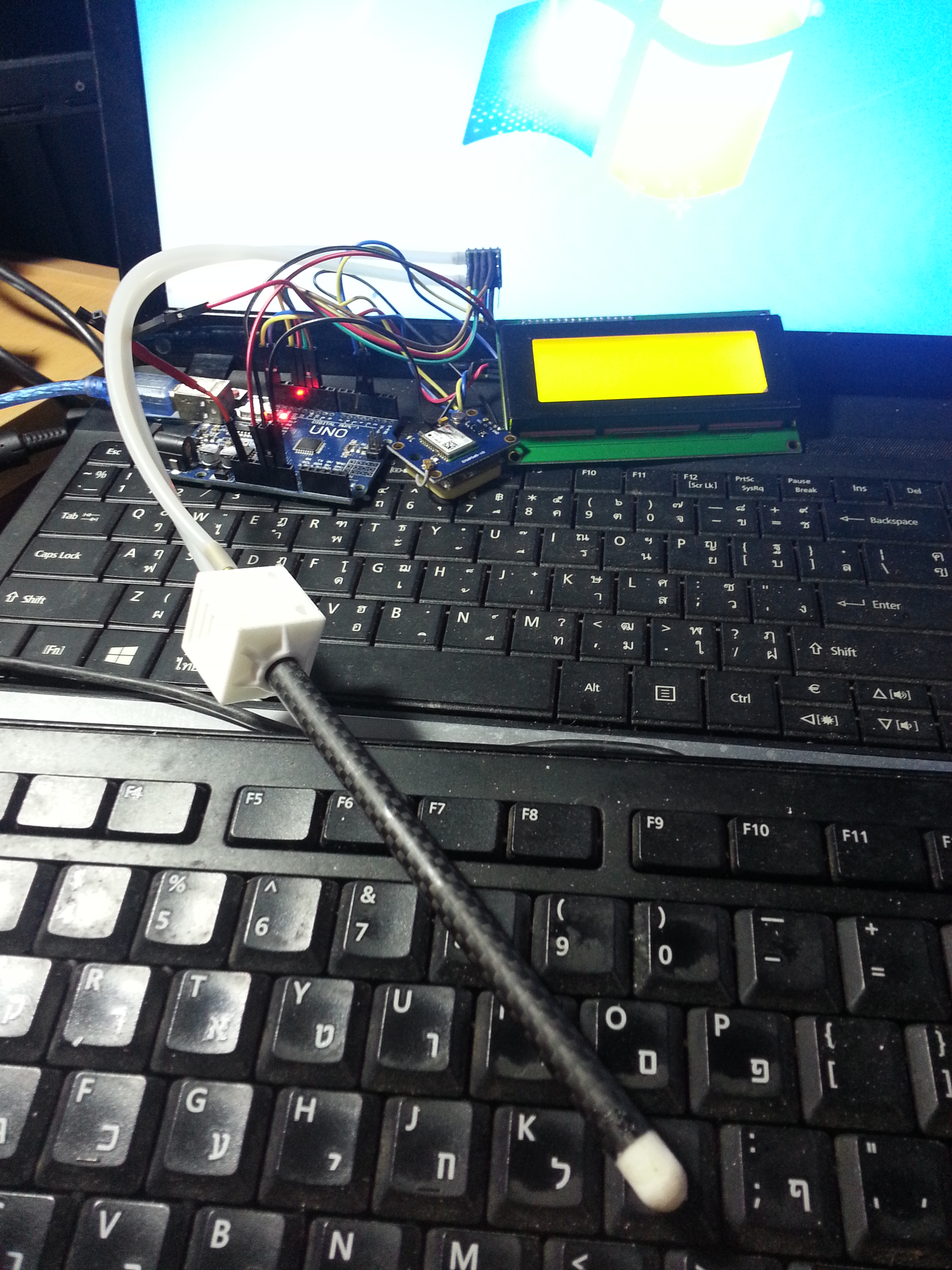
The setup of our reader, Itay
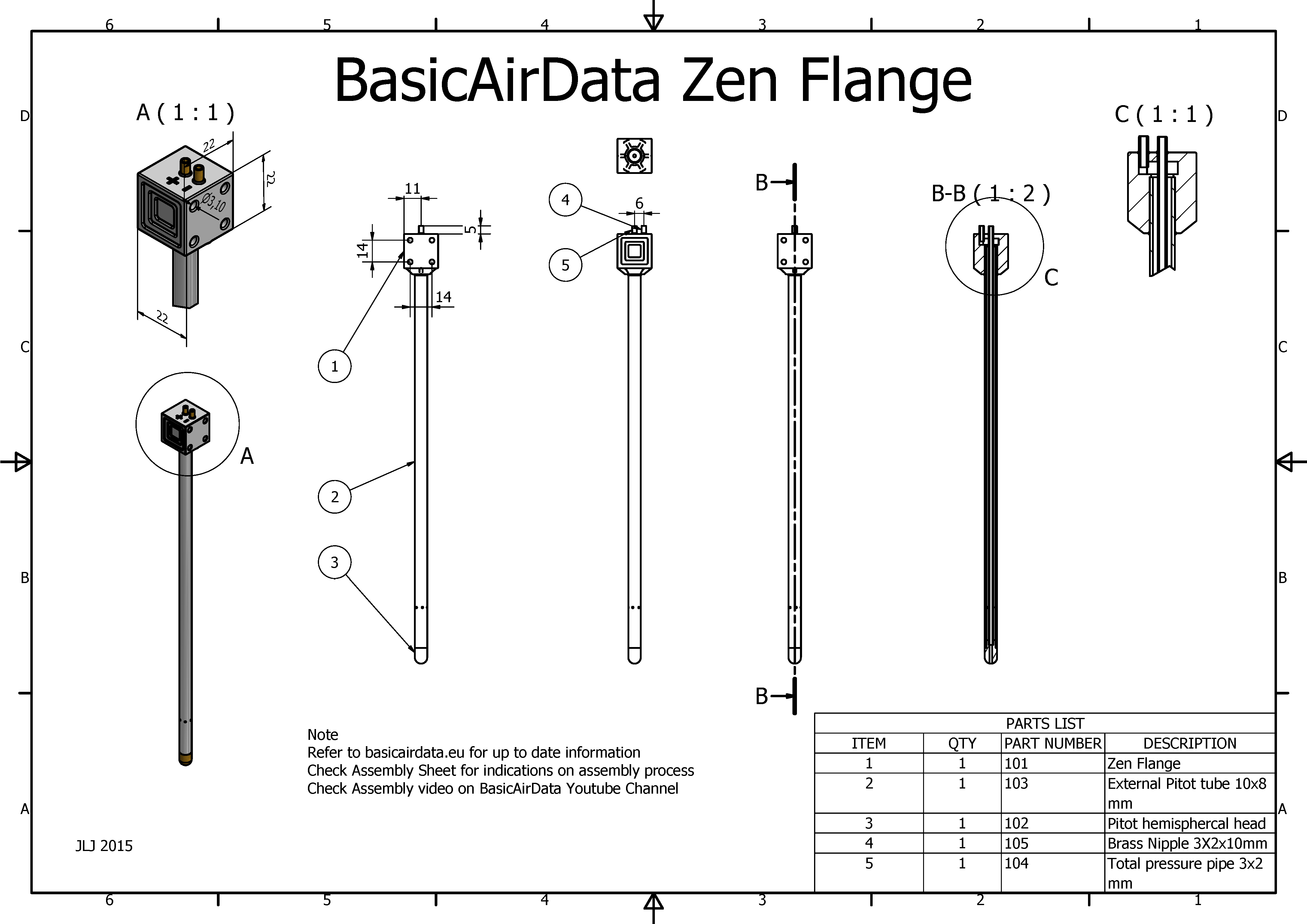
Figure 1: General Assembly Drawing
The assembly is fast and revolves around a signle 3D printed part (STL file). An assembly cheat-sheet can be seen in Figure 2.
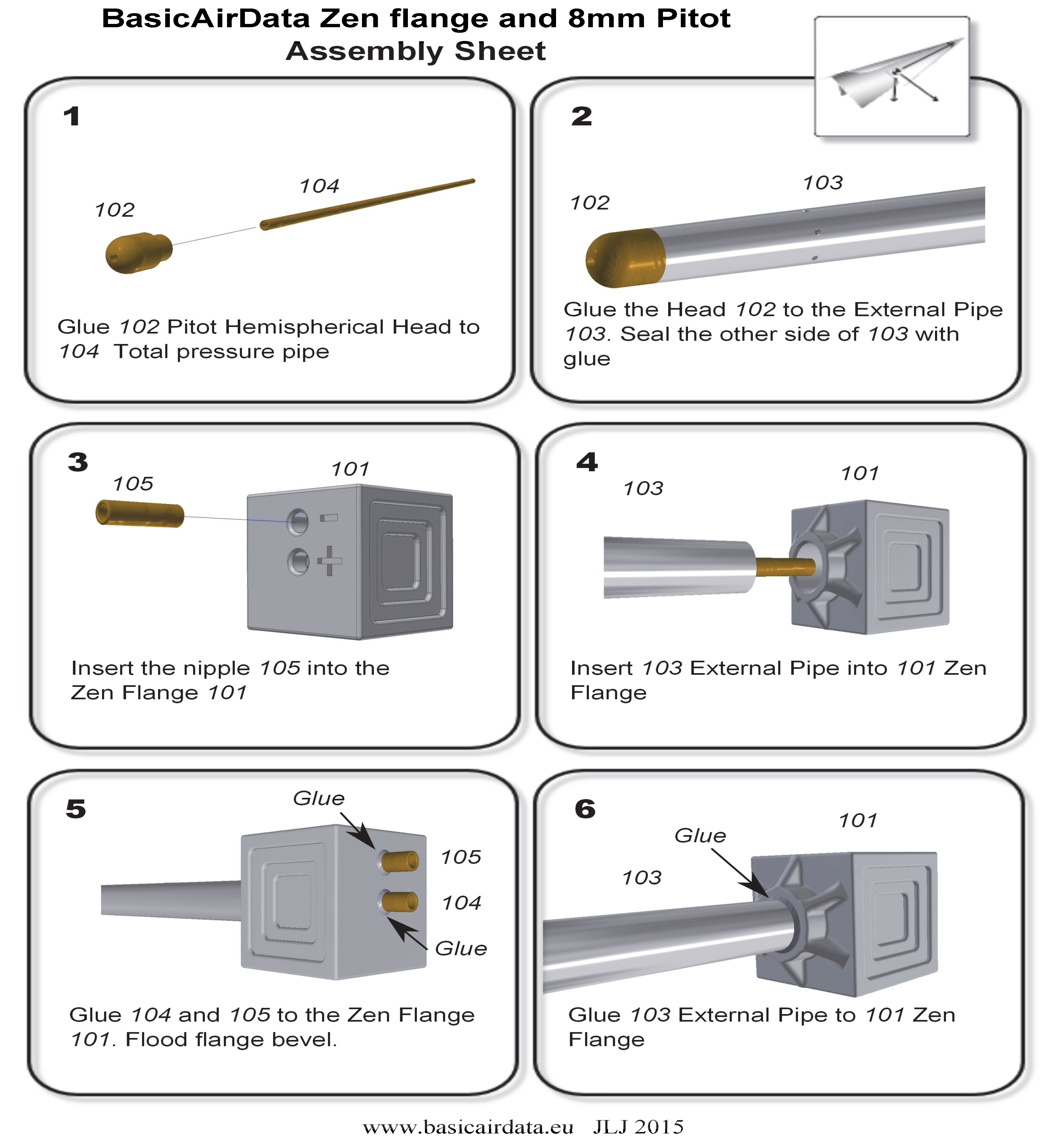
Figure 2: Assembly Sheet
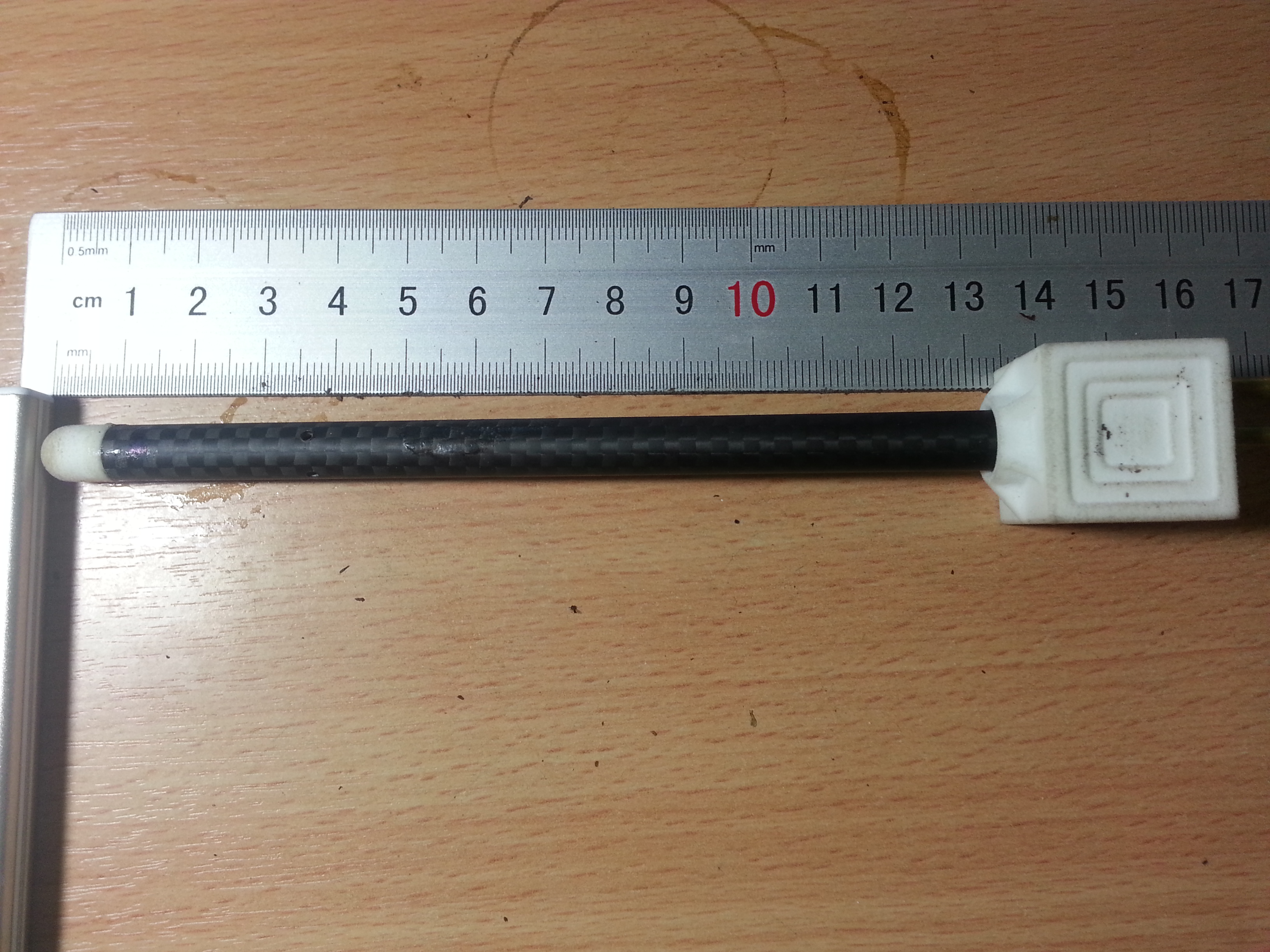
Figure 3: Printed Zen Flange
The assembly procedure doesn’t consist but of trimming three tubes and gluing the whole thing together. Let the overall length of your probe be L(mm), in our example L=200. The overall length is defined as the distance from the tip of the probe to the back of the flange, excluding the nipples.
- The external pipe has an outer diameter of 8mm and an inner diameter of 6mm. A carbon fiber tube is a good choice. Trim it at L-18mm, which is 182mm in our example.
- Drill the static pressure ports on the outer pipe, at a distance of 36mm from the front pipe end. Drill 8 holes of 1mm diameter, 45° apart. This procedure is identical to our previous probe model.
- Cut a nipple of length of 10mm (refer to assembly sheet item 105), for example out of a brass tube, with outer diameter of 3mm and inner diameter of 2mm.
- Cut the total pressure pipe (item 104) at a length of L-7mm (193mm in our case), for example out of a brass tube, with outer diameter of 3mm and inner diameter of 2mm.
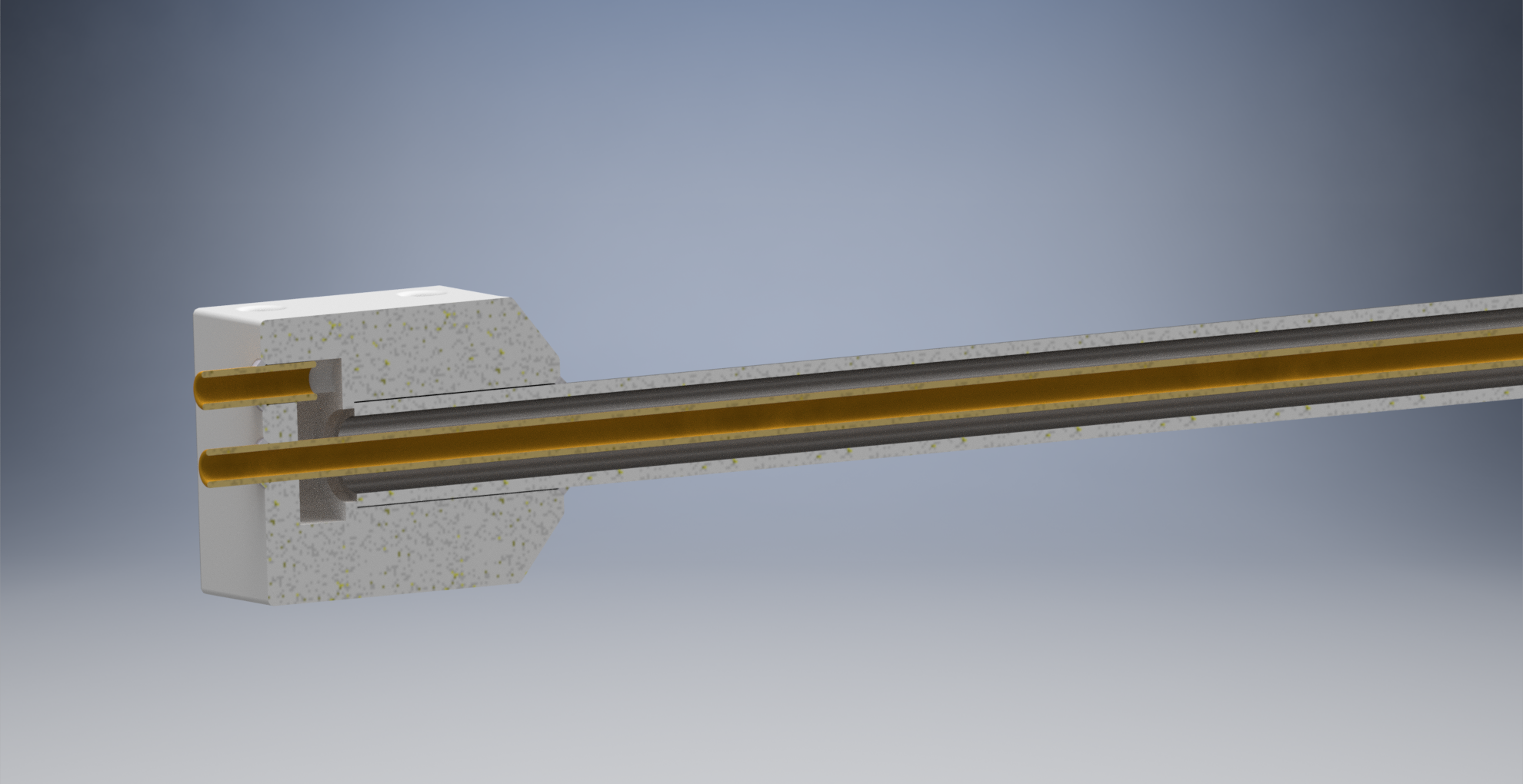
Figure 4: Rendered Section View
Video 1: Assembly Test Video
When you have prepared all the parts, make a little assembly check as per Video 1.
After a positive assembly check you can glue the pieces together. The important interface is that between the Pitot head (102) and the total pressure pipe (104). It is critical that this glue seal is airtight. Once you glue the external pipe (103) on the Pitot head you will not be able to repair any leaks.
Once you have glued all the parts together, you should test if the two pneumatic paths are free of obstacles and airtight. If it is available, a Pitot-static tester can be used. If not you can perform a quick test by following this simple procedure:
- Blow into the + nipple. The air should flow unobstructed down to the total pressure port.
- Seal the total pressure port with your finger and blow into the + hole. There should be no air leaks.
- Blow into the – nipple. The air should flow unobstructed down to the static pressure ports.
- Seal the static pressure ports with adhesive tape and blow into the – hole. There should be no leaks.
Congratulations! You have a new Pitot-static probe!