Manual for standard airborne use.
You find the previous pdf release of the 8mm pitot manual here.
Table of Contents
- Contact Information
- Introduction
- Installation Overview
- General Installation Layout
- Mechanical Setup
- Pneumatic Connection
Introduction
The measurement of the airplane velocity TAS/IAS, relative to the air-mass around it, is a common task on an instrumented aircraft. With airspeed data, it is possible to evaluate the aircraft dynamics and the aerodynamic performance; it is a fundamental measurement for system identification and control procedures.
Our probes are designed to be mounted on scale models. Use on manned aircraft is not certified and inadvisable. Be aware of your country legal restrictions regarding RC aircraft and relative devices. Always place safety first. It should be crystal clear to you that this probe is designed and tested to fly in the subsonic speed range and at a little altitude above the ground. Also, keep in mind that your probe performance and accuracy is directly related to the pressure sensor you are using and the air data processing units that translate the sensed quantities into useful data. This installation manual describes the main issues that can impact airspeed probe operation, reliability, and performance. Usually, the installation position affects the accuracy of static pressure, whereas total pressure, is only slightly affected. Even in a good installation position, the static pressure can differ by many percentage points from the actual value.
Installation Overview
For best performance, your airspeed probe must be properly installed. This brief guide describes some well-known procedures for installation and maintenance of airspeed probes. The airspeed measurement instrument is composed by two main subsystems; the primary one is the 8 mm probe that you’ve already built, and the secondary is everything else: from the pressure sensor to the calculation algorithms (e.g., an Air Data Computer). As the type and availability of the required hardware are diverse, we will try not to depend on a specific product solution. At first, we will describe alternative mounting positions; then we will introduce probe specifics characteristics and performance. Ideally, the airspeed probe should be infinitely long to minimize the static error, if it weren’t for mechanical limitations.
General Installation Layout
There are three widely used probe installation layouts. Here follows a brief description of each setup. The probe can be installed essentially anywhere, but the advantage of a standard mounting point is the possibility to use available experimental data and bibliography. On the contrary, if a non-standard installation position is chosen, the corresponding position error needs to be calibrated. Refer to the “Pneumatic Connection” paragraph for detailed pneumatic connection instructions. For detailed mechanical information on mounting points refer to the “Mechanical Setup” paragraph.
Wing Tip/Leading Edge Layout
 Reference page when the probe is mounted on the leading edge of the wing. It is necessary to keep it out of the propeller wake and far from the fuselage. In Figure 3 you can see an airspeed probe mounted on the wing tip. This type of installation is suitable for tractor propeller configurations. Its main drawback is a higher wiring and tubing complexity and the fact that roll dynamics affect the measurements. After probe placement, it is also necessary to add weight on the opposite wing to balance the airframe on the roll axis.
Given the wing chord, c, and the profile thickness at the installation wing section, t, then the probe length protruding from the wing, l, should be chosen equal to max(10t;1c). For example, if our wing has a symmetric NACA 0012 airfoil and a chord of 20cm, we get t=2,4cm and l≥max(24cm;20cm); so it should be greater or equal to 24cm. In another example, if we use a profile with c=20cm and t=1,5cm then l≥max(15cm;20cm)=20cm. At this probe length, the static pressure accuracy should be around 2% of the dynamic pressure.
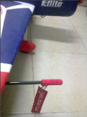
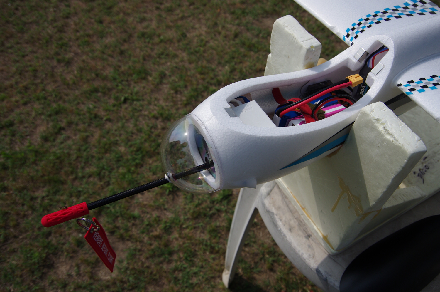
Nose Mount
Reference page when the probe is mounted on Nose. In this configuration, roll dynamics affect much less the probe performance, the probe is located inside nearly undisturbed air flow for a wide attitude range, and sensor wiring is easy. Usually, it is required to fit an internal dedicated mounting bracket to fix the probe in place.
 It is advisable to select a probe length, in front of the fuselage, greater than 1.3 times the maximum fuselage diameter or 1,5 the hydraulic diameter. The suggestions for wing tip installation are still valid for the nose installation: the longer the probe, the better the measurements.
Under Wing/On Wing Strut
It is easy to install the probe on the wing struts but the routing of flexible tubing and wire can be messy and flimsy, and the roll dynamics can strongly affect the measurement.
This installation is usually adequate for total pressure measurement only. To obtain the differential pressure reading, the static pressure can be sampled from a static port on the fuselage. If the Pitot-static probe is mounted under the wing but protrudes beyond the leading edge of the wing, it is possible to treat this case as a leading edge mounting installation.
Mechanical Setup
There are two main types of BasicAirData Pitot-static probes. The first one is without a flange and the second is with a flange. Since variants of the basic flange are available, it is possible to accommodate for different installation requirements.
Both systems are relevant and operational and it is up to you to choose what type fits your application best. Important factors to take into account while choosing are the overall dimensions of the equipment and how easily it will lend itself to use and mounting. Regardless of the mounting options you make, please keep in mind the following guidelines:
The Main axis of the probe must be aligned with the longitudinal axis of the airframe. Be careful not to damage or alter structural parts of the aircraft during installation. The mounting options for the probe are not restrictive: any custom configuration can be used, as long as it can withstand the aforementioned strain. In some cases, epoxy glue has been proven good enough to hold the probe in place.
Many methods have been used to mount a probe without a flange, with a clamp being the most common. It is readily available and easy to customize.
Pneumatic Connection
On the rear part of the probe or on the flange, you will find the two pneumatic connections; we call them the signal lines. Refer to the supplied assembly drawings: for the flanged model, the rear nipple is the total pressure port, the forward nipple is the static pressure port. For the non-flanged model, you should label the pressure ports during the assembly phase.
Blowing through the center hole of the probe, the air will escape through the total pressure port; the other pressure port is the static one. You can decide whether you will connect one absolute pressure sensor to each signal line, or you will treat the lines as a dual signal port and connect them to a differential pressure sensor. General connection schemes can be found in the “General Instrumentation Layout” section.
Be very careful not to bend the metal pressure lines of the probe, as the metal can suddenly crack. If that happens, repair works or component replacement may be needed. It is common for the first part of the tubing, about one centimeter, to be made out of Tygon or silicone tubing. After that section, the tube is coupled with a rigid section of tubing. That arrangement does not hinder performance and ensures good vibration decoupling between the probe, the sensor, and the tubing.
The overall pneumatic tubing should be as short and stiff as possible. Metal and nylon are appropriate materials. The lines should be free of obstructions and held in place during the flight. Do not allow the lines to move and bend freely. In many cases, for example, when low G-forces and low vibrations are expected, the use of silicone tube of high thickness can be acceptable. However, in the general case, silicon tubing can deform under oscillatory forces, which can lead to unwanted pressure changes. To avoid this fault, use instead of a pressure line made of rigid plastic material or metal, for example, brass. Many manufacturers of compressed air fittings have in their catalogs useful plastic tubes with outside diameter of 3-4 mm, often used in RC models for retractable landing gears.