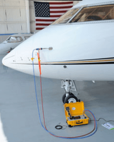
Figure 1 – Pitot test equipment fitted on a plane – https://www.dfwinstruments.com
Prior to any data collection endeavor, it is advisable to test the response of the airspeed sensor through the entire span of the measured quantity. Such procedures are followed on equipment installed on commercial airliners and private airplanes. In this article, a general method is presented, which can be used in a DIY context.
Moreover, a test rig is presented and a simple design for a pressure source is proposed. Finally, an example data file for the calculations is provided.
During a basic Pitot probe calibration, the total and static pressure ports are pneumatically connected to a test instrument. The instrument applies a sequence of pressures and records the corresponding airspeed readings. More elaborate test equipment also simulate the variation of static pressure with altitude and temperature.
Moreover, after a period of time has passed since the initial calibration, it is necessary to verify that the equipment under test performs the same over the full operational region.
To minimize test equipment cost and complexity, in a DIY fashion, only the really basic tests will be carried out. The test procedure will verify the correct functionality of the software/hardware solution for airspeed measurement.
Setting up the requirements
For demonstrational purposes, we will apply the test procedure to an imaginary Pitot probe linked to a differential pressure sensor, whose measurement range is 12,5 mBar or 1250 Pa.
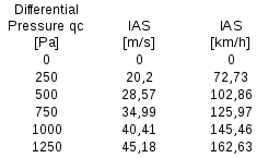
Table 1 – Ideal, no uncertainty, input-output characteristic of a Pitot
This is a reminder of the IAS definition:
(1) 
Where 
Using equation 1, it is possible to calculate the following table.
This table represents the ideal relationship between measured differential pressure and indicated airspeed.
To personalize your table, you can use the provided experimental.xls spreadsheet.
We record  samples of input differential pressure and the corresponding Pitot IAS. The mean of the pressure measurements and IAS measurements will be recorded on a table and used during the acceptance test.
After a complete test run, we get a table similar to the Table 2.
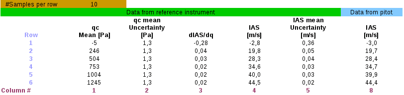
Table 2 – Example measurements results and IAS calculated values
An important part of testing is to source a stable platform, or test rig, that allows us to work in a comfortable way.
Furthermore, a reasonable criterion to define the test equipment requirements is to do so based on the required Pitot probe performance.
In this case, we require:
- Static pressure range: 130 000 Pa to 90 000 Pa;
- Differential pressure range: 5000 Pa;
- Pneumatic connections should avoid condensation to reach reference manometer/s;
- The rig should allow the operator to 1) Connect the static with the total port; 2) Insulate pressure ports; 3) Drain condensation;
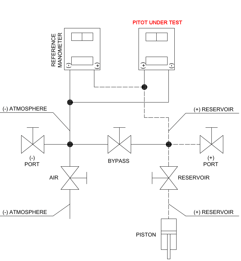
Figure 2 – Calibration rig layout scheme
These requirements are incorporated with the DIY requirement
- Reduction of part count and overall cost
The proposed test rig layout is shown in the Figure 2.
Test rig operations
Until now we’ve talked about testing the airspeed sensor, neglecting all practical aspects. A brief description of the actual operation is presented. The connections to reference instrumentation and to airspeed sensor are based on a widely used layout: the five valve manifold or instrumentation manifold.
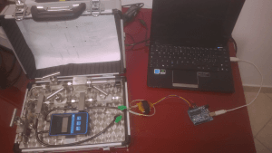
Figure 3 – Example test rig
At the beginning of test procedure all valves are closed.
The first operation to be accomplished is the connection of the reference differential pressure manometer and the pressure ports of the Pitot tube. The total pressure port should be connected to the (+) line as well as the instrument high pressure port.
Commonly used sensors have a very little internal volume. The connection of a pressure line, which essentially is the insertion of a plastic tube to an instrument nipple, will cause a sudden rise in the internal pressure. To avoid the sudden pressure rise, the “bypass” valve should be left open during the whole operation.
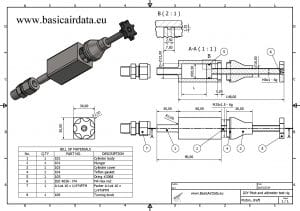
Figure 4 – Example of piston drawing
– If already present condensation should be removed, open valves “(+)” and” (-)”.
– Then open “(+)” and “reservoir” valves and unscrew the piston knob to the full back position.
– Close “(+)” valve.
– Connect instruments and close the valves ”(+)””(-)” and “bypass” , open the “air” valve.
Now it is time to zero your reference instrument. This is a function available on almost all digital instruments, refer to manometer manual for details. After zeroing, the differential pressure reading should be exactly zero.
Turn the piston knob clockwise to reach the desired test differential pressure.
Once the test pressure has been reached, close the “reservoir” valve. This operation is essential to avoid problems with piston leaks.

Figure 5 – One piston prototype with the reservoir valve
If your reference manometer is capable of taking “average” measurements, then only wait until the desired number of samples has been collected and note the average value. If your reference manometer logs only the current value, then carefully note the desired number of samples and compute the average.
Do the same to get IAS measurements.
Repeat the procedure for the next test pressure point: open the “reservoir” valve and turn clockwise the piston knob to increase the pressure. As you see, the procedure is quite simple, but some precautions should be taken during the design and use of the test rig.
General recommendations
Pressure lines should not be made of flexible material. This will avoid the risk to have a pressure reading modified by the variation of line volume. A short flexible pressure line segment can be acceptable, but it is recommended to use a high thickness tube. Good construction materials are metal and rigid plastics; do not use silicon tubing.
- The drain lines outlet must be below any other point of the pneumatic circuit. Drain lines routing should not obstruct the flow of condensation. A minimum slope of 5° is recommended.
- Pressure lines connections of each instrument should lie on the same plane.
- All components of the test equipment and the equipment under test should be placed in the test room a few hours before the test.
- Turn on the pitot electronics and the reference manometer at least one hour before the test procedure.
- The electronics used to power and operate the Pitot probe should be the same as those that will be used during normal operation.
- Work in a room with a mild temperature, around 20 °C is a good value.
Test rig design
The precedent pneumatic circuit can be implemented using every kind of standard valves, tubing and fittings available on the market. The material of these components is not important, as long as it does not deform. The test rig on the next picture has been made of stainless steel. In the past the author used plastic drip irrigation components.
Every component, except from the pressure source, is available in regular hardware stores. Initial design guidelines do not allow for the use of an electronic pressure controller. These devices can be directly driven by a micro-controller to provide a closed loop regulated pressure (page 2) and are the best choice for a fully automated operation.
Since requirements for the calibration rig included low cost and manual calibration then this device have been replaced by a simple hand-operated piston.
Since the test rig should be suitable for Pitot probe and altimeter calibration, we should select the desired maximum altitude and airspeed. Let’s assume that we want to calibrate an altimeter up to 3000 meters Using the barometric altitude formula <BAD link> we can estimate that our cylinder should be capable of generating 70 kPa, starting from an air pressure at 101,325 kPa.
Alternatively stated, this is a variation of pressure of -31,325 kPa. If we set the maximum calibrated airspeed  to 50 m/s, using the basic pitot formula we require a variation of pressure of
  .
.
At this point, you should take the higher differential pressure value, which usually is the altitude differential value, and use that as your requirement.
Now that we have the differential pressure requirement, let’s increase this value by a 1,5 safety margin factor. In our example case this corresponds to 46988 Pa.
Afterwards, we need to estimate the volume of the pneumatic circuit. You only need to take in to account the volume of the tubing between the piston and the pressure tap. We don’t need any precise calculation of the internal volume of valves or any other minor volume; A rough estimation is enough. Let’s assume that we are using a tube with an internal radius  of 3e-3 m and with a length lt of 0,4 m. We can calculate the approximate pressure line volume
Note that the piston assembly in figure 4 is provided with a knob that can accurately move the plunger back and forth. It is possible to increase or decrease the pressure in a very smooth manner. To relieve the O-ring from friction is a good idea to lubricate the piston internal surface. If you use a nitrile O-ring a good choice for lubricant is silicone grease.
Let’s assume an internal piston diameter D of 21 mm.
So what is the piston stroke L needed to reach the required pressure?
When the plunger is moved, the volume of the air in the pressure line is changed, consequently the pressure changes. Let’s assume that this process is adiabatic: no heat is exchanged with the environment.
We define  as the initial air volume and
  as the final air volume. The air has a molar mass of 28,96
  and heat capacity ratio
  of 1,4.
  is the pressure of air with volume and
  is the pressure of air with volume . To determine the piston stroke length, we calculate the maximum differential pressure that under the adiabatic compression assumption and using the gas law we get:
![\[P_2=P_1 {\left(\frac{V_2}{V_1}\right)}^{\displaystyle - \gamma_{air} }\]](https://basicairdata.eu/wp-content/ql-cache/quicklatex.com-55bc7efd45a0f7c1e61e304b8bc86475_l3.png "Rendered by QuickLaTeX.com")
Launching “adiabatic.sce” Scilab file, and setting an initial value of 25 mm for full stroke lenght value, we get 
P1 Initial pressure 101325 Pa
P2 terminal pressure 224582 Pa
Maximum differential pressure 123257 Pa
Differential pressure after one knob turn 4371 Pa
P2/P1 2.2
Table 2 “adiabatic.sce” output
We previously mentioned that our differential pressure requirement was  , so the selected stroke is suitable for our requirements.
Such a simple model does not account for piston leaking; this problem will not affect calibration as long as the “reservoir” valve is shut off during the pressure measurements.
For a comfortable use of the test rig oversize L to compensate for leaks. This way, there will be no need to refill the piston with atmospheric air during a basic calibration cycle.
Another parameter to set is the plunger screw pitch. This corresponds to the desired pressure variation per knob turn; too high a value can lead to a piston which is really uncomfortable to operate. A good initial value seems to be 2000 Pa per knob turn,  . That leads to choosing a piston with an internal diameter around 15mm.
By no means is a pressure difference of 5,5Pa per degree of knob rotation is a hard requirement.
A piston with 21 mm of internal diameter has been used with no loss of operator comfort. For easier operation, use a big knob diameter, the bigger the better.
Reduction of the internal diameter leads to increase of the piston stroke, in order to achieve the desired pressure range. A graphical representation of sizing parameters relationship is found in figure 7.
An analytic solution of the sizing problem is implemented in the last part of adiabatic.sce.
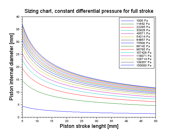
Figure 6 – Cylinder diameter vs screw pitch deltap turn constant Sizing chart piston stroke vs diameter, deltap constant
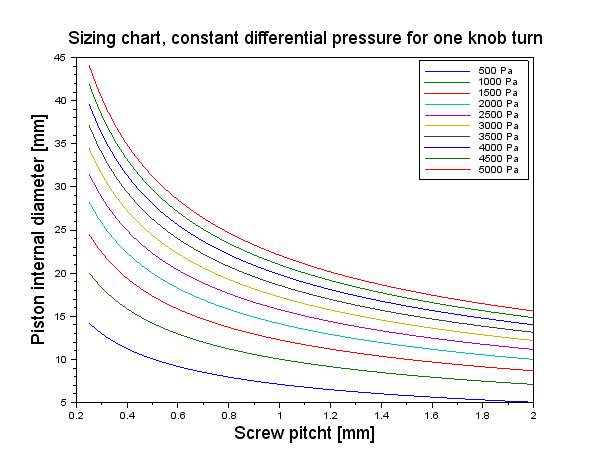
Figure 7 – A graphical representation of sizing parameters relationship