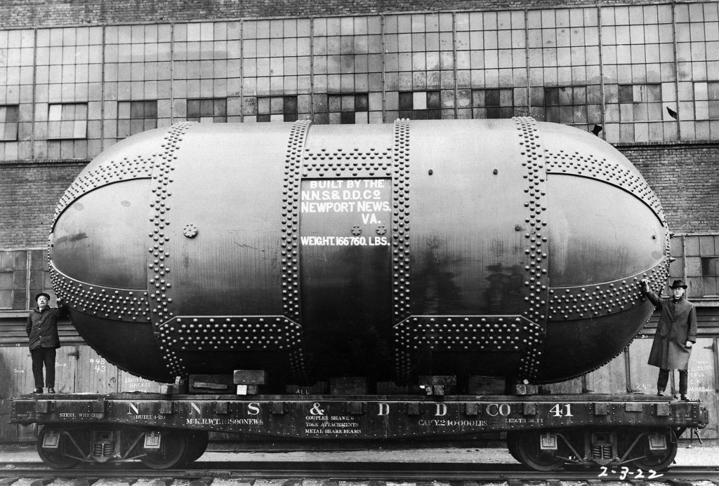
The Variable Density Tunnel was a wind tunnel at NASA’s Langley Research Center
In wind tunnel calibration and CFD simulation, we should deal with the fact that our testing conditions are not the same of operating conditions. For example, it is typical to use scaled models rather than full-scale prototypes. We need some way to correlate the results obtained with the scaled model to the real world situation. We will draft a procedure to achieve such a result. First of all, we need to operate in similar aerodynamic conditions. To do so we should work with an identical geometry, in such a situations the flow over the body have the same pattern under the same aerodynamic conditions.
For example, we will consider two probes [Mechanics of Flight, 2nd Edition, Warren F. Phillips], the first with a diameter of  and the second with a diameter of
  . As the second geometry is obtained scaling the first probe geometry by a 0.5 factor over the three dimensions, we will consider the two to have an identical geometry. For the data obtained with the two probes to be comparable, we need to search for an aerodynamic similarity.
At a glance, the main two aspects to deal with
- To find a minimum set of variables that describe our experimental setup
- To handle geometry scaling and aerodynamic similarity
The dimensional analysis is the right tool. This method allows us to individuate a set of base quantities systematically and reduce to the minimum amount of required experimental data.
If we apply the Buckingham  theorem under the nonviscous and noncompressible flow assumptions, we get that a single dimensionless parameter aerodynamically describes our flow over the probe. That parameter is the Reynolds number
  , where
  is the airspeed,
  the fluid density,
  is the dynamic viscosity of fluid and
  a geometric characteristic length. Number of Reynold for our example probes are
  and
and  . Let’s pretend that we have a wind tunnel and conduct a test for airspeed probe calibration purposes with a scaled probe of diameter
  . The temperature during this trial is 23°C, pressure 101 325 Pa, relative humidity 50%, airspeed is 20 m/s. Using operative conditions we calculate the air density
  and viscosity
  and
and .
.
As per the dimensional analysis, we can use the results of our test with a similar geometry probe and at the same Reynolds number. For example, how does relate the experimental result to a full-size probe at the same operating conditions?
We calculate  and by inversion
 .
.
The full-size probe behavior is similar to that of the scaled probe at the double of the airspeed.
That simple example also clarifies why have been built pressurized wind tunnels.