There are many methods to increase the performance of our movable surfaces, we introduce here the spades, we will give also an introductive numeric example. Spades are mechanical devices that can provide a better static and aerodynamic balance of ailerons or elevators movable parts.
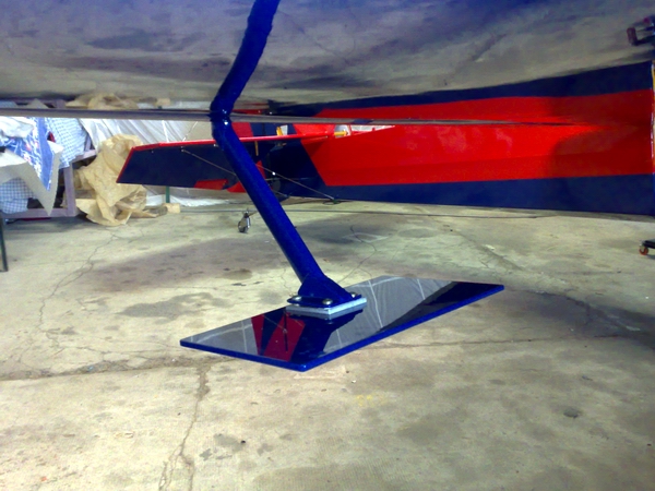
Figure 1 Laser 260 spades
You can find that kind of device even on small general aviation planes, Figure 1 shows Laser 260 spades. The spades can be seen as a combination of a plain mass balance weight with an aerodynamic surface, they are usually installed with a bracket fixed to a movable surface. It is to be mentioned that a simple mass balance solution can avoid premature wing-aileron flutter[1] (Figure 6, Year 1923). The main advantage of spades is that the required torque to operate the control surface in flight is reduced. Sizing of spades comes after a preliminary sizing of the control surfaces; spades will not increase the performances derived of a poorly selected servo. If we desire a fast response we should choose high torque servos, the bigger the better is a popular and reasonable criterion.
Refer to Figure 2. In the figure there are shown the forces and moments acting on a generic aileron movable surface, the remaining part of the wing is considered rigid. For example, let’s the wing chord be  of 0.5 m and the aileron chord
  70e-3 m; suppose that the airfoil profile is a symmetrical NACA 0012 and the wing have a rectangular planform with
  wingspan; ailerons are present along the whole wing trailing edge.
We have four families of forces acting on the movable surface, aerodynamic, servo force, mass, and inertia. Aerodynamic forces are the lift, drag, and moment; in order L,D, and M. That forces are applied on the center of pressure of the aileron that lies at a distance cp, for our example 17.5e-3 m. from the hinge axis O.
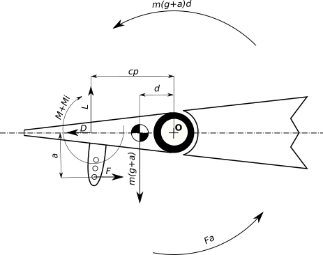
Figure 2 – Forces and moments acting on a generic movable surface
The magnitude of this forces is dependent on the airspeed and on the aileron geometry. The servo force, F, is acting on the servo horn. Servo force equivalent torque on the aileron hinge is Fa, where a is the arm of the force. Mass-related force is indicated as mg and consist on the contribute from the balsa wooden made aileron mass  . Inertia is present in two terms; mMa term accounts for the center of gravity current acceleration a, set to 0. This term of inertia generates an equivalent torque M(g+a)d , where d is the distance of the center of mass from the aileron hinge, for our example we will assume
  .
.
The term of moment  is due to the angular inertia, where
  represents the surface deflection respect the neutral position (in Figure 2,
  ). By inspection of Figure 2 is evident that the servo contrast constantly the torque generated by the mass and inertia forces. To avoid that we can to reduce the arm d.
Refer to Figure 3. Let’s pretend we have studied the moment at hinge with  and we have determined that maximum total aerodynamic moment on one aileron has a value of 0.15 Nm (roughly 1.5 kgcm) for the desired maximum design airspeed
  of 40m/s or 144km/h.
With a counterweight of mass  placed at a distance
  from the hinge axis the center of mass moves exactly over the aileron hinge axis. In Figure 3 the effect of aileron mass is ideally compensated.
Except  , that increases, all the other physical quantities still the same. Is to be noted that with that device it is possible to reach a perfect balance only for the given aileron deflection ; as the aileron deflects the center of mass will move, of course in many practical cases that aspect will not hinder performances.

Figure 3 – Balance mass added to the aileron
The position of the mass changes is leverage effect, a distance  is a good first guess value; the ratio between distances is also the inverse of the ratio between the aileron and the counterweight mass.
Now let’s focus on the aerodynamic contribute of spades, refer to Figure 4. We note that the center of pressure of the spades should be placed beyond the aileron hinge towards the leading edge. The aerodynamic design of the spades is similar to that of any lifting surface, the extra constraint is that weight should be that desired to balance the aileron. As design parameter ,we will impose the torque contribution at the hinge. A first guess value is 20% of the required maximum operative torque in the worst case scenario, commonly at maximum  ; the value for our example is 0.030 Nm.
Here come into play some design trade off. The higher torque I require from the spades the stiffer should be the mount point and the aileron itself on the other side receive more torque from the spades mean increasing performances. We should consider also that to have top performances we should keep a low aileron moment of inertia, that requirement is going opposite direction respect the high stiffness requirement. A low moment of inertia and a strong spades contribute will lead to having, with the same control force F , a quicker movement of the control surface. On human piloted aircraft there is also to consider the feeling of the pilot about the control force, a near to zero required force can result to be not comfortable for some pilots; that aspect is totally negligible on RC or similar platforms.

Figure 4 – Aileron deflected with aerodynamic forces from a spade
Back to our example, we decide to use spads composed of a 1.5 mm carbon fibre flat plate. We can use for our analysis the results from the thin airfoil theory. We will design the plate to give the required torque when the aileron is full deflected down, the flow over the plate will separate at a certain angle of attack  , let’s pretend we know that an angle of attack is 11°. From the thin airfoil theory we get the section coefficient of lift
  . The center of pressure of a flat plate, for small and medium/high aspect ratio lies at a distance of a quarter of the chord
  of the lifting surface. The center of mass of a flat plate is located at the center of the plate. Lift force of the plate is
  , where
  is the area of plate. Substituting our values, for a plate with chord
  , we get
  . So the required area of the plate is
  . And then the width of the plate
  . If we desire to increase the effect of the device we should just increase , for W_p=59e-3 we get a surface providing the 40% of the required hinge torque. The weight of a carbon fiber plate 20x60x1.5 mm is under a gram. To obtain the required mass balance we need to reach
  with a mere ballast. The preliminary design is complete, now it’s necessary to proceed to the detail engineering. We shall consider more accurately the aerodynamics, and account for the inertia and mass of the mounting bracket; we will stop here for now.
Note that the final design and performances rely on an accurate requirement phase that provides the desired torque. The flutter, inertia and total mass consideration are interesting topics and deserve it’s own space in further to be published material.