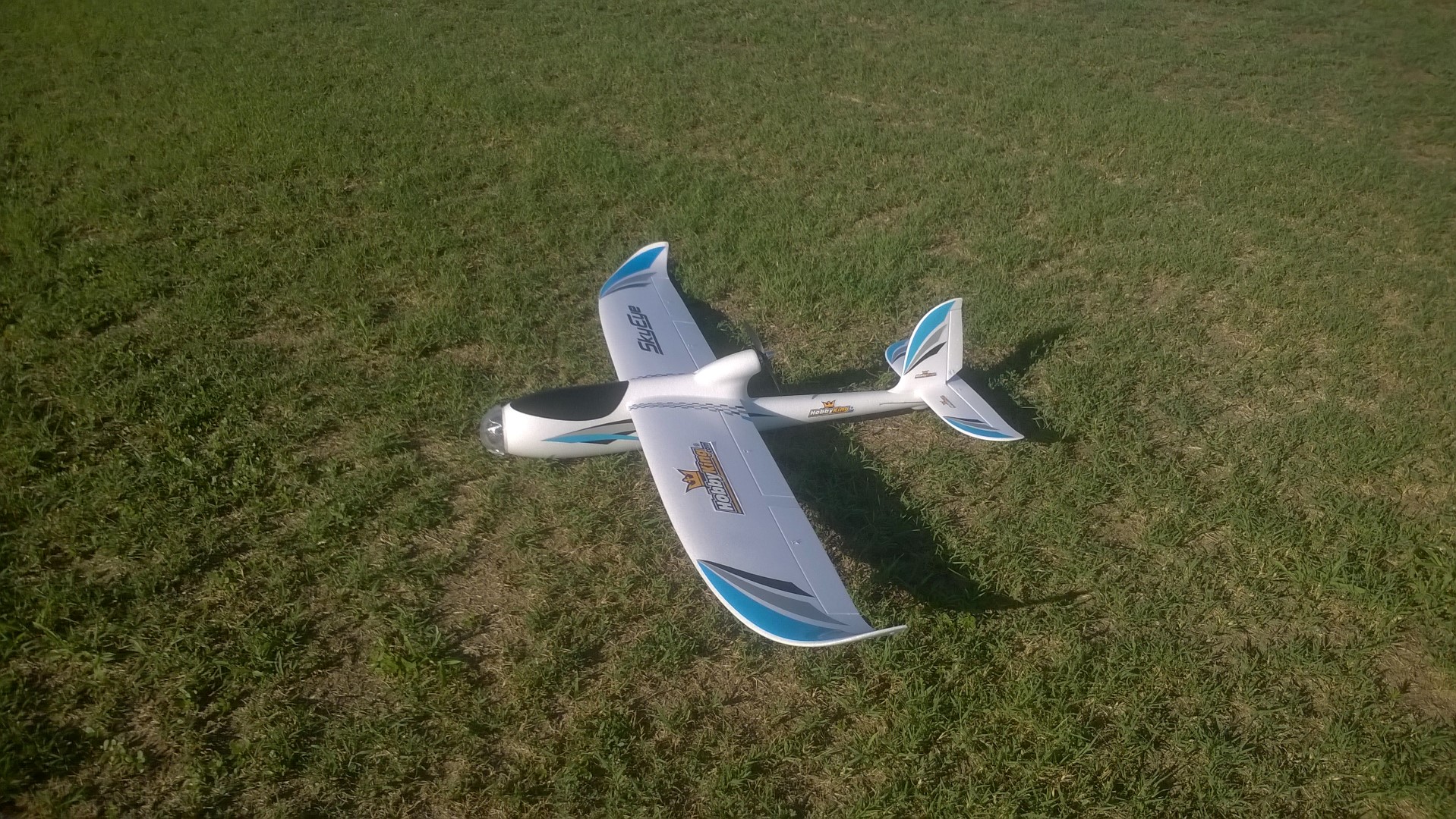
Some time ago we assembled an RC plane for flight test. Selected model was the Sky Eye by Hobbyking. Assembly was carried out by JLJu and MT, both members of Basic Air Data Team; the whole process took one night to be completed. Open a browser at this link to visualize some pictures of the process. The model arrived with all the necessary hardware except the receiver, the transmitter, and the foam glue.
The first operation is to fix the horizontal stabilizer and the vertical stabilizer with the foam glue, the tail comes with pretty nice joints and the coupling warrants a good alignment of all the parts. Despite that when you leave the glue to cure check carefully that the horizontal stabilizer and the wing are 0° degrees apart, also check that the vertical stabilizer and the horizontal stabilizer are at 90°. Next step is to fix the servo horns to the airplane movable surfaces, four on the wing and two on the tail. Each servo horn is supplied with a plastic plate and four screws to fix the horn to the control surface. In fact, positioning is trivial as there are mounting marks on the foam. We used both glue and screw for all the horns. Leave the glue to cure totally.
The second part regards servo link connection and radio setup. On out TX, we created a new program for a plane with ailerons and flaps. Then we connected the two provided extension cables. Finally, we connected the servo leads to the receiver; there are labels on all the provided servo leads [If you are interested in control the four wing servos in an independent way, for example for butterfly, you need to buy four servo extension cords]. Now turn on the receiver to check the servo travel and neutral position, connect the servo link rods to the servo horn of all the surfaces. Be careful that in neutral stick position the control surface should be in a neutral position too, correct any misbehavior regulating the length of the control rod.
Our ESC was working good from the box (Check the ESC manual), we reversed the throttle channel and set the travel on the TX. Check and eventually program the ESC without mounting the propeller. From the tail, the rotation direction of the propeller should be clockwise. Attach the propeller firmly with the provided nut. Advised COG position is 71 mm from the wing leading edge; it is on the wing main spar. To get the COG in the right place, we put two batteries side by side against the front bulkhead.
You can see that assembly is straightforward, KIT is well conceived and packed. You can be ready for the airfield in less than four hours!