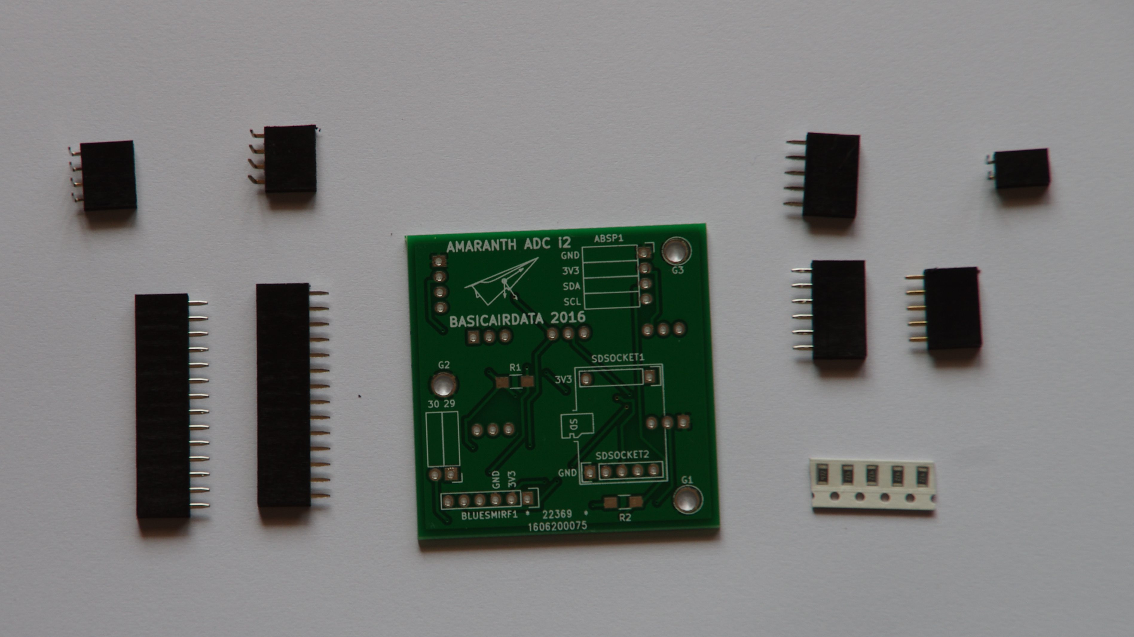
Sockets and custom PCB for Amaranth i2 ADC
Printed Circuit Board procedure for ADC Amaranth i2. Prior to proceed through this tutorial, please be sure to have all the components reported here.
It’s supposed that the user is already trained is basic soldering skills. The PCB dimensions are generous compared to the mounted components, no particular care is needed.
1. Solder the four SMD 4.7kOhm resistors
Refer to the video tutorial. In short, you should tack one side of the resistor, using the plier, and then you finish the other side without any other help.
During this operation, you can lay down the PCB on a small piece of fabric.
2. Solder the Sockets
We soldered the components in the following order, and everything goes well. You will notice that some pins should be stripped off for the socket to fit on the board. To remove the pin from the receptacle just pull out the pin with a plier. Measure twice cut once.
- SDSOCKET1, straight 5 pins (remove pins 2-3-4)
- TSONE1, straight 14 pins (remove pins from 4 to 11)
- TSTWO1, straight 14 pins(remove 4-5 and 9-10-11)
- SDSOCKET2, straight 5 pins
- ABSP1, 90 degrees 4 pin
- DELTAP1, 90 degrees 4 pin
- BLUESMIRF1, straight 6 pins
- P1, 90 degrees 2 pin
Now that you have finished the PCB proceed to COTS preparation.