Measurement of aerodynamic parameters like angle of attack, sideslip, and true airspeed can be performed with pressure based probes; they can be used on all types of terrestrial and nonterrestrial vehicles. These probes are able to reconstruct the desired measurement using information about the pressure distribution over a probe.
VectorProbe MHP
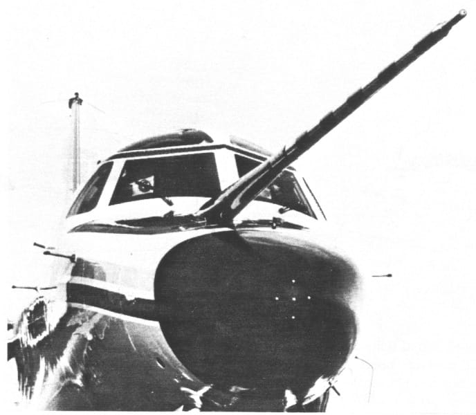
The mechanical probe can be built on purpose or in particular cases geometrical features of the vehicle may be used as probe surface, like on the NCAR plane you see on the following picture.
Multi-hole probe (MHP) technology is suggestive because don’t need for moving parts to operate. That is a way to get rid of the inertia related limitations of classical wind-vane sensors, nevertheless, the MHP sensor probe is small, self-contained, and robust.
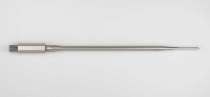
You can see an example MHP probe head on the following picture from a commercial website.
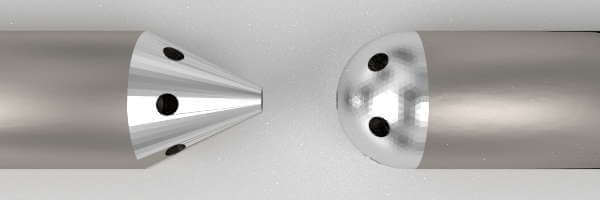
Returning to classical MHP, the major advantages seems to be the robustness, absence of moving parts, extremely fast response and a capacity to operate at high incidence angles. Typical MHP has five holes facing the airstream; four holes are in a cruciform pattern and the last on the center line.
In this post, we will expose the multi-hole basic theory, based on an ideal probe, the probes measure the angle of attack.
To simplify the example we assure the angle of sideslip is zero; hence the cylinder axis of symmetry lies on a plane perpendicular to the wind vector plane. As we need a closed form solution for the pressure field, we also adopt the incompressible and inviscid flow hypothesis. That case is in in-depth studied in specific literature. Under our working hypothesis the analytical result will be by far different from the experimental result(for a wide Re range); in different
Figure 3. Stream lines around the cylinder
On the
So under our working hypothesis the pressure will be function only of the angular distance  .
.
Introducing the dimensionless coefficient of pressure 
For our particular case  , according to equation 4.117 in this link.
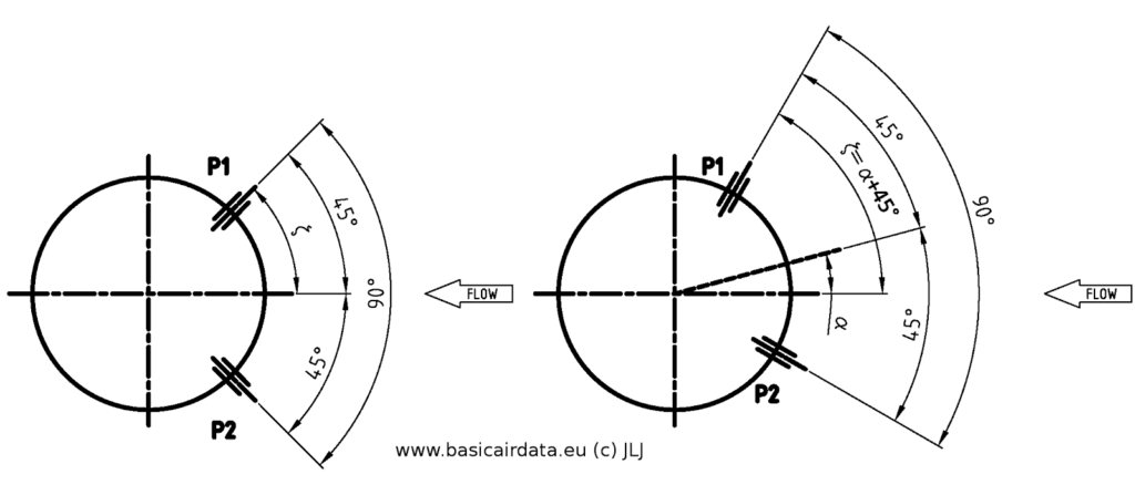
Refer to figure 3. Note that pressure distribution is symmetrical and  for
for  . Recalling that the holes are 90° degree apart, to account for AOA
  we define
  .
.
With the given  expression is possible to calculate the pressure in correspondence of each pressure tap,
  for different values of . The MHP calculation spreadsheet is here.
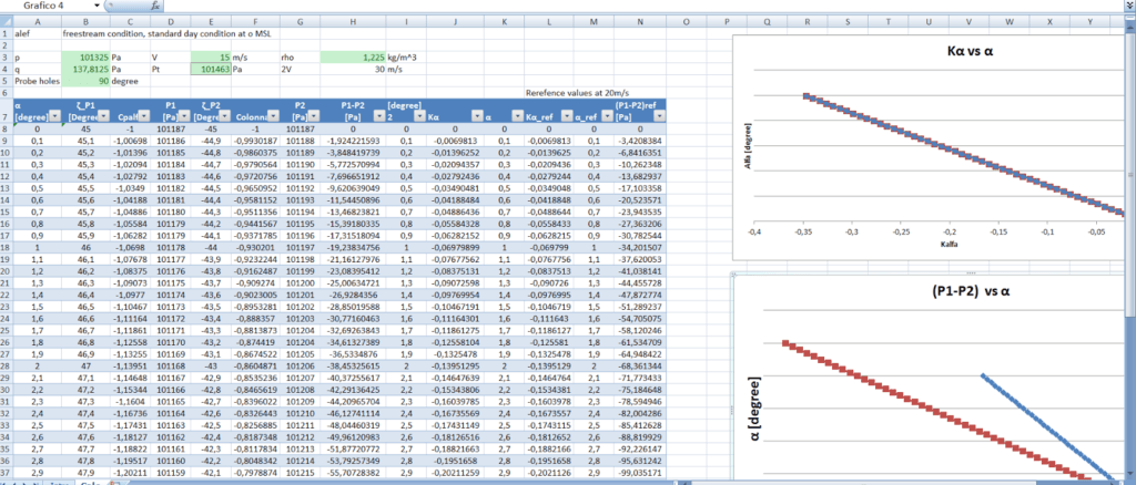
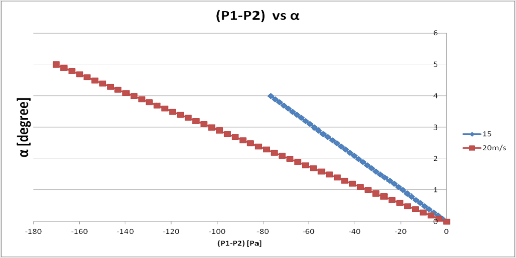 at two different speeds
 By inspection of table 1 and
It is possible to obtain a calibration coefficient constant with the airspeed, it is called coefficient of and is defined as  , where
  is the total pressure.
Refer to the below figure for a graphical representation.
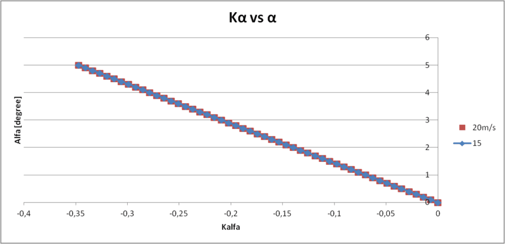
Reportrd results are valid