In the case where our telemetry data is used for system identification purposes, health management or similar tasks, the need for an indication of our sensor reading accuracy arises. It simply makes no sense to take the trouble to produce elaborate telemetry data if it’s not known how reliable the result is. As an example of air data usage consider a system that checks real time data from the Pitot tube, the GPS and the engine thrust to evaluate subsytem failure status [1].
Below I outline the procedure for total uncertainty calculation. Details and the calculation routines will be presented in each instrument specific page. Refer to international standard [2] for a detailed description of uncertainty.
Consider the following measure  ,
,  , Gaussian.
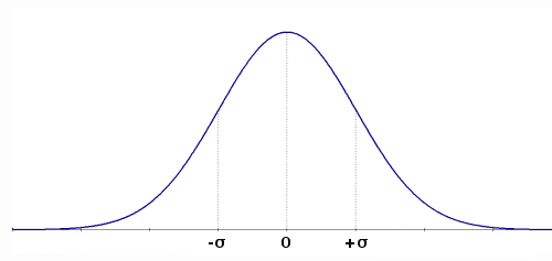
The term inside the parenthesis represents the uncertainty and  is the coverage factor that in this example leads to a 68% confidence level due to the Gaussian probability distribution. Thus we know that with a probability of 68% the real value lies between 5,0V and 5,2V.
For example purposes let’s pretend to measure the value of resistance of a resistor. One straightforward manner is to measure the voltage at the resistor leads and the current flowing throught it at the same time. The value of resistance is then the ratio between voltage and current.
Given:
 , Gaussian (Voltmeter uncertainty)
 , Gaussian (Ameter uncertainty)
 , where
  and
and 
To calculate the final uncertainty we use the propagation formula A3 from NIST [3], correlation terms have been neglected as we assume the two uncertainties are not correlated.
Therefore uncertainty, considering only instrumentation information, is equal to:
![\[u(R)=\sqrt{{\left( \frac {1} {i_b} \right) }^2 (uv_b)^2+(v_b)^2+(ui_b)^2 }\]](http://www.basicairdata.eu/wp-content/ql-cache/quicklatex.com-fb79296b0123e0d4b615928a08ddab03_l3.png "Rendered by QuickLaTeX.com")
So the value of the resistance is 1,00(0,14)ohm. According to paragraph six of this reference, since the first digit of 0,14 after the comma is “1” to express uncertainty two decimal places should be used.
The uncertainties in the example are given and are of type B. Sometimes these may need to be estimated from measurements of the instrument at hand. Reference [1] Sect 4 reports an exhaustive definition of type A and B of uncertainty.
In this link you can find a simple Scilab file to carry out the calculation. You can arrive to the same results using many different tollboxes as NISP.
In the presented calculation any impact of the test apparatus, as connection resistance, is neglected and the math model for the resistor is kept on purpose very basic.
At a glance
To obtain an usable measure by an instrument:
- Define design goal uncertainty;
- Gather uncertainty for every employed sensor;
- Define measurement involved hardware and software;
- Search for all the possible sources of added uncertainty;
Main aspects to consider to increase accuracy:
- Use higher performance sensors;
- Use calibration data to eliminate know errors;
- Use Sensor accredited laboratory calibration data;
- Oversampling;
- High order modeling;
- Periodic sensor test and recalibration;
References
[1]Søren Hansen, Mogens Blanke, and Jens Adrian, “Diagnosis of UAV Pitot Tube Defects Using Statistical Change Detection,” 2010 [Online]. Available: https://orbit.dtu.dk/fedora/objects/orbit:59518/datastreams/file_5164484/content. [Accessed: 17-Apr-2013]
[2]JCGM, “Evaluation of measurement data — Guide to the expression of uncertainty in measurement.” JCGM, 2010 [Online]. Available: https://www.bipm.org/utils/common/documents/jcgm/JCGM_100_2008_E.pdf. [Accessed: 17-Apr-2013]
[3]NIST, “A method of evaluating and expressing uncertainty in measurement adapted from NIST Technical Note 1297.” 1994 [Online]. Available: https://www.nist.gov/pml/pubs/tn1297/index.cfm. [Accessed: 17-Apr-2013]