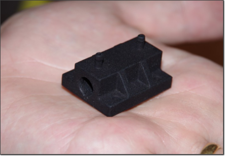
Figure 1: Pitot flange with barbed ports
Assembly indications
After prolonged use of the standard 8 mm pitot tube some installation problems have been reconsidered and solved, so now the classical model can be suited with a fixation flange. To speed up your work you can find here a 3D .stl file of the assembled probe, check the animation of the model. The use of the two brass pipes as impulse lines is simple but they can’t be trimmed near the pitot body, if they are shortened or bent around likely they will leak or break away, therefore overall dimensions are considerable. A workaround for this issue is to build a flange that can route air to a standard barbed port, so a new design was put to test. In Figure 1 the finished pitot flange, you download a 3D model for the pitot flange here.
Other parts still the same of the classic probe, static pressure pipe is not needed anymore. The length of 8 mm pipe and total pressure 3 mm pipe should be adapted to the desired finished pitot length as follow. Given L as the total assembled length, the 8 mm pipe finished length should be then L-27mm and the 3 mm pipe length equal to L-12mm, in the Figure 2 L=200 mm so 8 mm pipe is 173mm and 3 mm pipe is 188mm. All the required parts are depicted in Figure 3.
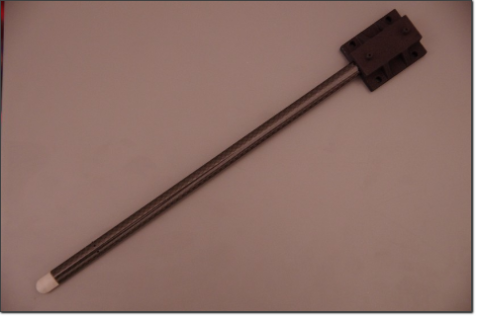
Figure 2: Assembled pitot with flange, carbon fiber 8 mm tube
I publish some pictures of the main assembly process steps, for the assembly, you will need:
- Epoxy bicomponent resin, 5 minutes fast curing
- Work in a heated room, the epoxy resin has problems to cure below 20°C (check your resin manual)
- Scissors
- Electrical tape
- Sandpaper 600-800 grit
- Paper sheets
- Some toothpick or another similar disposable object to apply the resin
Assembly process can start once you have cleaned all the parts and you have checked the fit as per Video 1. You should use the sandpaper to prepare the surfaces that will be joined with the resin.
So prepare the pitot head to be glued to the 3 mm tube, sand at least 10mm on the pipe and clean the part, and sand also the flat at the top of the pitot head. Carefully seal the head part with the Electrical paper, your pitot head should look like Figure 4.
Test the cure position, that should be head down, like the picture 5.
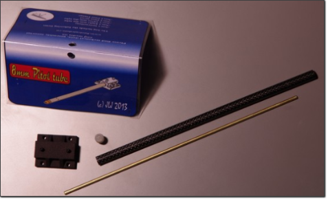
Figure 3: All the parts needed for the pitot
Cover your working plane with white paper, mix few grams of epoxy resin and with a toothpick lay a generous amount of resin at about 4 mm from the pipe tip, just like the picture below. The resin should not enter the pipe (Figure 6).
As the resin has a medium viscosity keep turning the pipe until you finally put in into the pitot head and then leave it to cure (Figure 7).
After the resin is cured remove the electrical tape and you should get the result in Figure 8.
After that this crucial part is completed test the if the joint is airtight, ahead of the assembly will be impossible to correct any defect.
If the head is airtight you can proceed to the final assembly phases, every time you make a new glued joint it’s a good practice to check the airtightness.
After the assembly only two operations are left, they are the pressure taps drilling.
With a pillar drilling machine and a 1 mm dia bit make the total pressure hole, the farthest from the pitot head, with a deep of 13 mm the other hole should be drilled 10.5 mm deep.
A figure of drilling is reported in Figure 9.
During the drilling process check if the drill has broken through the pipe wall blowing into the total or static ports.
Now your probe is ready to be fitted with the sensors.
Proceed to air data computer section for a description of the required hardware software to operate your pitot.
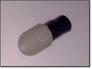
Figure 4: Pitot head ready to be glued
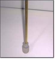
Figure 5: Position to be held to cure the resin
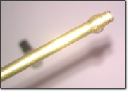
Figure 6: 3 mm pipe with resin
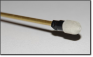
Figure 7: Total pressure pipe glued
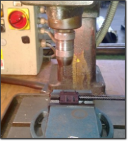
Figure 9: Drilling of the pressure taps
Video 1: Necessary material
Video 2: Instruction to assembly flanged pitot